USB 2.0, released in April 2000, represented a major advancement in performance and functionality over USB 1.1. It introduced a High-Speed mode with a data transfer rate of 480 Mbps, a significant improvement over the 12 Mbps offered by USB 1.1. USB 2.0 Key features included backward compatibility with USB 1.1, allowing older devices to connect to USB 2.0 ports, and an enhanced power supply of 2.5W (5V at 500mA), enabling support for a wider range of bus-powered devices.
USB 2.0’s high data transfer rates and improved power capabilities made it the standard for connecting peripherals such as external hard drives, printers, and scanners, driving widespread adoption across consumer electronics and becoming the dominant standard for many years.
DC Specification of USB 2.0
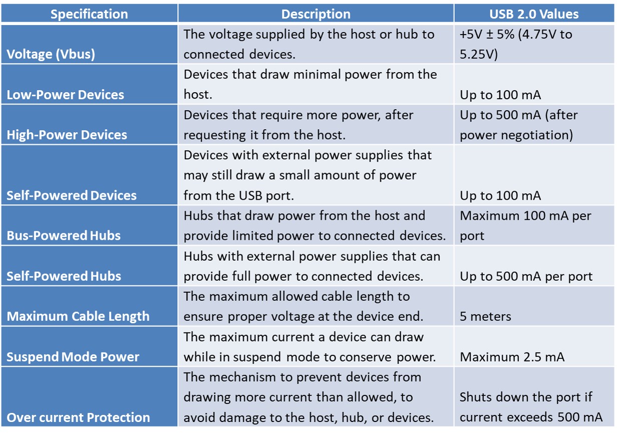
The USB 2.0 DC specification defines the electrical characteristics of power delivery over a USB connection. In USB 2.0, power is supplied over the same cable that carries data, allowing devices to be powered directly by the host without the need for an external power source. The specification defines how much current and voltage a USB 2.0 device can draw from the host or hub.

Components of USB2.0
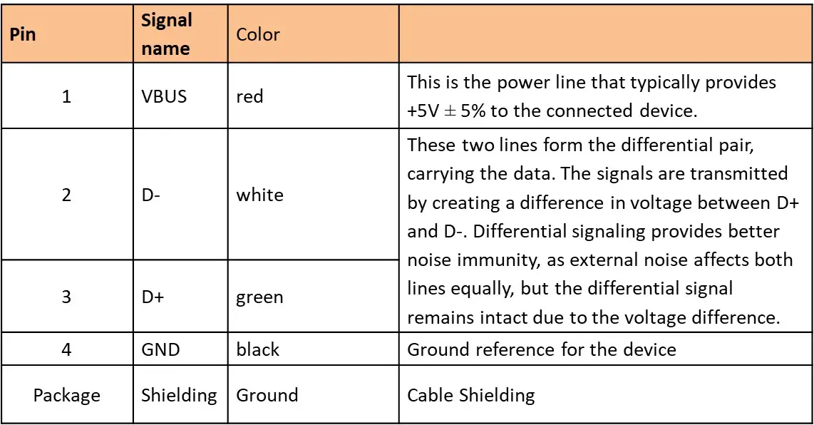
USB 2.0 Signal & Pin Assignments
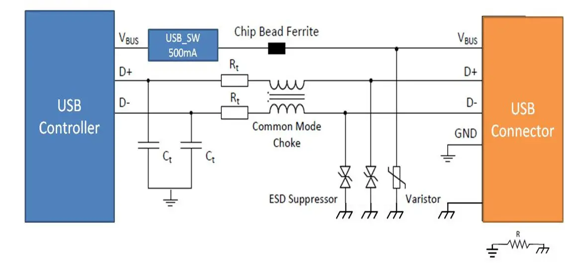
USB2.0 Circuits
The image shows a USB 2.0 interface circuit with the necessary protection designed to ensure the proper functioning of USB, addressing signal integrity and protecting against electrical transients and electromagnetic interference (EMI). USB components and their roles are explained below.
 USB Controller
A USB controller is a hardware component (Integrated Circuit) that manages communication between a host device (like a computer or embedded system) and USB peripherals. It handles data transfer protocols, device enumeration, and power management, ensuring smooth communication through differential signaling on the D+ and D- lines.
USB2.0 controller supports various data transfer types (control, bulk, interrupt, isochronous) and operates at different speeds, such as low-speed (1.5 Mbps), full-speed (12 Mbps), high-speed (480 Mbps). It implements the USB protocol, manages bandwidth, prevents signal collisions, and protects against errors with mechanisms like error checking and retransmissions.
Additionally, it controls power distribution (e.g., 5V in USB 2.0), handling up to 500mA or more for high-power devices, and supports suspend/resume functions to save energy.
USB controllers can function as hosts (in computers) or devices (in peripherals) and are essential in managing the plug-and-play functionality of USB devices. They are found in motherboards, embedded systems, and USB hubs, enabling seamless connection and communication between the host and multiple devices.
USB Switch
USB power switches are MOSFET power switches that limit output current to 500 mA as specified by USB 2.0. When the output load exceeds the current-limit threshold or a short circuit is present, the device limits the output current to a safe level by switching into constant-current mode, pulling the overcurrent logic output low.
The USB interface is intended for dynamic attachment and detachment (hot plug/unplug) of peripherals, which are considered hot-plug applications. Such implementations require control of the current surges experienced by the main power supply and the card being inserted.
The most effective way to manage these surges is to limit and slowly ramp the current and voltage applied to the card, similar to how a power supply normally turns on. These devices can be used to provide a softer start-up to devices being hot-plugged into a powered system.
Chip Bead Ferrite
The chip bead ferrite, placed on the Vbus line, functions as a high-frequency noise filter that blocks interference while allowing DC current and low-frequency signals to pass. USB cables can pick up electromagnetic interference (EMI) from surrounding electronic devices, and this noise can enter through the power line, potentially disrupting sensitive components.
The ferrite has its maximum impedance in the range of approximately 80 MHz to 500 MHz, where the highest level of interference is expected during USB data transmission. Above 200 MHz, it becomes primarily lossy & acts like an ohmic resistance without reactive components.
Termination Resistors (Rt)
The resistors are placed on the D+ and D- lines for “impedance matching”. USB data lines are transmission lines that require a specific characteristic impedance (typically 90Ω for differential pairs) to prevent signal reflections. Without proper impedance matching, signals can reflect along the line, leading to distortions and data errors.
The value of the termination resistors can be derived using a signal integrity (SI) tool. The termination resistors ensure that the impedance of the data lines matches that of the USB cable, improving signal integrity and maintaining proper voltage levels during data transmission.
Common Mode Choke
The common mode choke filters out common-mode noise on the data lines. In a differential pair (D+ and D-), noise that affects both lines equally is known as “common-mode noise”. The choke suppresses this noise while allowing the differential signal (the actual data being transmitted) to pass through unaffected.
It plays a crucial role in minimizing electromagnetic interference (EMI), ensuring that the USB device remains immune to noise from surrounding electronic equipment and preventing the USB cable from radiating noise that could interfere with other devices.
The choke works by using inductors that are coupled together to block common-mode signals by presenting high impedance, while allowing differential signals to pass with minimal loss.
Capacitors (Ct)
Decoupling and filtering capacitors are typically used to decouple high-frequency noise and filter out voltage spikes on the D+ and D- lines. In high-speed communication lines like USB, any high-frequency noise can cause signal distortion, data errors, or malfunctions.
These capacitors smooth out spikes by shunting high-frequency components to ground, leaving the main signal unaffected. They are carefully chosen to have low impedance at high frequencies, ensuring that unwanted high-frequency noise is filtered out without affecting the actual data signal.
TVS/ESD Suppressors
Transient voltage suppressor/Electrostatic discharge (ESD) suppressors are designed to protect USB circuitry from sudden electrostatic discharge events that can occur when a user connects or disconnects a USB device.
These diodes, function like safety valves; they remain inactive during normal operation voltage but conduct excess energy to ground when a high-voltage spike, such as an transient voltage or ESD event, occurs. This action prevents the excess energy from reaching and damaging the sensitive electronics in the USB controller.
Select TVS/ESD suppressors based on the design requirements. The following standards are useful for the USB interface and may vary according to specific design needs:
- Protection against ESD pulses according to EN 61000-4-2
- Protection against surge pulses according to EN 61000-4-5
- Protection against EFT pulses according to EN 61000-4-4
ESD suppressors are crucial in USB circuits because USB devices are frequently plugged and unplugged, making them particularly susceptible to ESD. By protecting against damage caused by static electricity, these suppressors ensure the reliability and longevity of the USB interface..
USB Ground
Ground (GND) serves as the reference point for all voltages in the circuit, ensuring consistent voltage levels across components and facilitating reliable power delivery and signal integrity in the USB interface. It connects to protection components such as capacitors, ESD suppressors, and varistors, providing a low-impedance path for noise and transient voltages to shunt unwanted signals away from sensitive components, thereby preventing interference with USB communication lines.
A well-designed ground plane is critical for reducing electromagnetic interference (EMI) and enhancing overall stability by minimizing loop areas that can pick up noise, while also contributing to safety by providing a secure path for fault currents, protecting both the circuit and users.
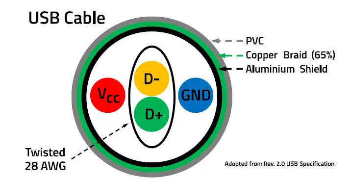
USB2.0 Cable
The cable consists of four wires, each precisely defined. The data wires are 28 AWG (American Wire Gauge), while the supply wires range from 20 to 28 AWG. This defines the diameter and copper resistance of the USB cable. The two supply wires are untwisted, while the data wires are twisted around each other, resulting in a differential mode impedance of 45 Ω or 90 Ω (+/-15%) relative to ground.
The cable length must not exceed 5 meters. If longer lengths are needed, a USB hub must be connected in between.
USB2.0 Connectors and Ports
USB 2.0 Summary
USB 2.0, launched in April 2000, improved significantly over USB 1.1 with data transfer rates of up to 480 Mbps (High-Speed), compared to USB 1.1’s 12 Mbps.
It maintained backward compatibility and enhanced power capabilities, providing 2.5W (5V at 500mA), supporting a wide range of bus-powered devices. It became the dominant standard for connecting peripherals like hard drives, printers, and scanners.
DC Specifications: USB 2.0 delivers power via the same cable used for data, enabling devices to be powered by the host. It supports:
- Voltage (Vbus): 5V ± 5% (4.75V to 5.25V).
- Low-Power Devices: Up to 100mA.
- High-Power Devices: Up to 500mA.
- Suspend Mode Power: Maximum 2.5mA.
Speed and Rise Times:
- Low Speed (LS): 1.5 Mbps, rise time 75-300 ns.
- Full Speed (FS): 12 Mbps, rise time 4-20 ns.
- High Speed (HS): 480 Mbps, rise time 500 ps.
USB 2.0 Components:
- USB Controller: Manages communication between the host and peripherals, handling data transfer protocols, power management, and error checking. Supports various speeds (LS, FS, HS) and data transfer types (control, bulk, interrupt, isochronous).
- USB Power Switch: Limits output current to 500mA, protecting against overloads.
- Chip Bead Ferrite: Filters high-frequency noise on the Vbus line.
- Termination Resistors: Ensures impedance matching for signal integrity.
- Common Mode Choke: Filters common-mode noise, reducing EMI.
- Capacitors: Decouple high-frequency noise and filter voltage spikes.
- TVS/ESD Suppressors: Protects circuits from electrostatic discharge events.
- Ground: Provides a reference point for consistent voltage and EMI reduction.
USB 2.0 Cable: USB 2.0 cables consist of four wires, supporting a maximum length of 5 meters. Data wires are twisted for differential signaling (90Ω impedance).
USB 2.0 Connectors:
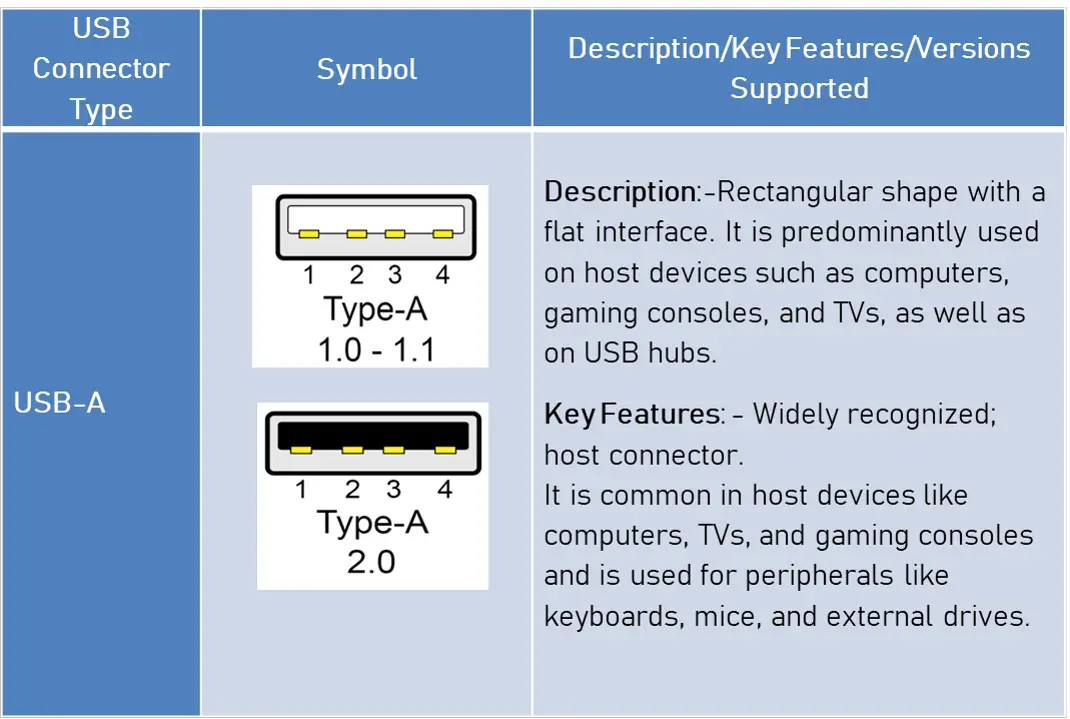
- USB-A: Common for host devices like computers.
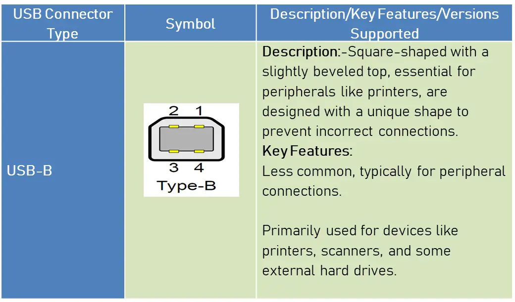
- USB-B: Typically used for peripherals like printers.
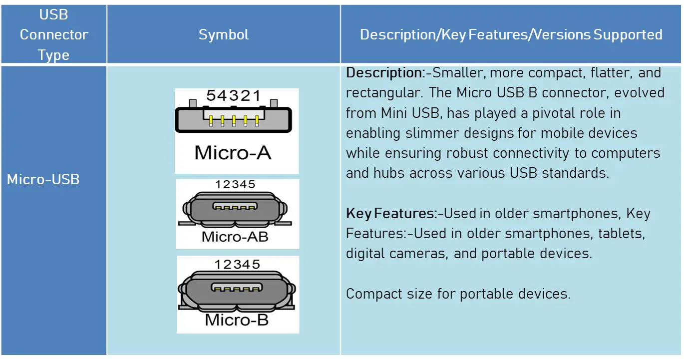
- Micro-USB: Compact for portable devices, used in older smartphones.
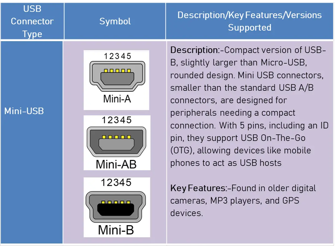
- Mini-USB: Used in older devices like cameras and MP3 players.
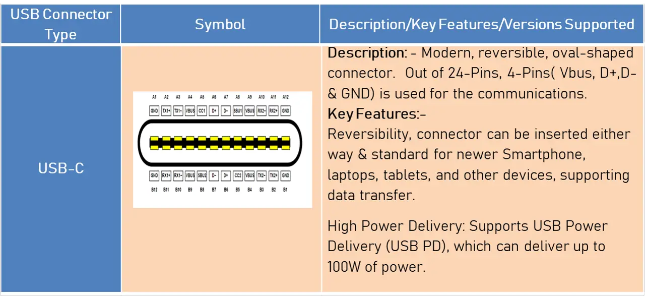
- USB-C: Modern, reversible connector for newer devices, supporting higher power delivery (up to 100W).
Author Profile
- 20+ years embedded hardware design professional with a burning passion for teaching. Sharing the intricate world of embedded hardware is my mission and joy.
Latest entries
 Tech Updates30 November 2025STM32WBA6: The Next-Generation MCU Powering Secure Short-Range Wireless Designs
 Blogs24 November 2025High-Speed PCB Layout Design Guide-104
 Tech Updates14 September 2025Renesas Launches RL78/L23 Ultra-Low-Power MCUs to Power Smarter Home Appliances
 Blogs7 September 2025High-Speed PCB Layout Design Guide-103


