A resistor is a passive electronic component that opposes the flow of electrical current through a circuit. It is designed to have a specific resistance value, measured in ohms (Ω), which determines how much it restricts the flow of electrons. The fundamental purpose of a resistor in electronic circuits is to control the amount of current that passes through various parts of the circuit.
How do Resistors Work?
Resistors work based on the principle of electrical resistance, which is the property of a material to impede the flow of electric current. They are passive components that do not introduce any amplification or energy conversion in an electronic circuit.
Instead, their primary function is to control the amount of current flowing through a circuit by offering resistance to the flow of electrons.
Here’s how resistors work in more detail:
Atomic Structure:
The behavior of resistors is rooted in the atomic structure of the materials they are made of. Most common resistors are made from materials like carbon, metal films, or metal wire. These materials have electrons that are somewhat loosely bound, allowing them to move relatively freely through the material.
Electric Field and Electrons:
When a voltage (potential difference) is applied across the ends of a resistor, an electric field is established within the material. This electric field exerts a force on the loosely bound electrons, causing them to move through the material in response to the voltage.
Resistance:
As the electrons pass through the conductor, they encounter resistance due to collisions with atoms and other electrons within the material. These collisions slow down the electron flow, transforming some of the electrical energy into heat energy. This heat dissipation is why resistors get warm when current passes through them.
Ohm’s Law:
Ohm’s Law is a fundamental principle in electronics that describes the relationship between voltage, current, and resistance in a conductor, such as a resistor. It was named after the German physicist Georg Simon Ohm, who first formulated this law in the 1820s.
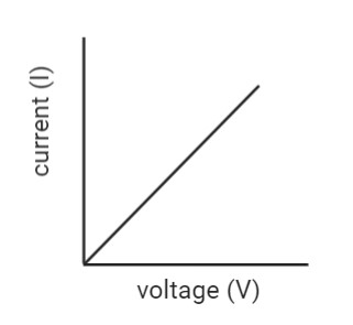
The relationship between voltage, current, and resistance in a resistor is described by Ohm’s Law, which states that the current passing through a resistor (I) is directly proportional to the voltage across the resistor (V) and inversely proportional to its resistance (R).
The formula for Ohm’s Law is:
Ohm’s Law states that:
“At a constant temperature, the current flowing through a conductor is directly proportional to the voltage applied across it, and inversely proportional to the resistance of the conductor.”
Mathematically, Ohm’s Law is represented by the equation:
V = I * R
Where:
V is the voltage across the conductor (measured in volts, V).
I is the current flowing through the conductor (measured in amperes, A).
R is the resistance of the conductor (measured in ohms, Ω).
Ohm’s Law is a fundamental tool for understanding and designing electronic circuits, as it allows engineers and hobbyists to calculate the expected current flow through a resistor or any other component based on the voltage applied and the resistance value. It is one of the cornerstones of electronics and is widely used in circuit analysis and design.
Resistance Value:
The resistance value of a resistor is predetermined during its manufacturing process. It is specified in ohms (Ω) and indicates how strongly the resistor opposes the flow of current.
Higher resistance values result in lower current flow, while lower resistance values allow more current to pass through.
Tolerance:
Resistors are manufactured with certain tolerances, indicating the acceptable deviation from their stated resistance value. For example, a resistor with a 5% tolerance and a stated value of 1,000 ohms could have an actual resistance between 950 ohms and 1,050 ohms.
By adjusting the resistance value, engineers can precisely control the current flow in electronic circuits, making resistors essential components in various applications like voltage regulation, signal conditioning, current limiting, and more.
They are widely used in everything from simple LED circuits to complex microcontrollers and sophisticated electronic devices.
Understanding Resistance, Voltage, and Current in a Resistor
Understanding resistance, voltage, and current in a resistor is crucial to comprehending the behavior of electronic circuits. Let’s break down each concept:
Resistance (R):
Resistance is a measure of how much a material or component opposes the flow of electric current.
It is represented by the symbol “R” and is measured in ohms (Ω).
The higher the resistance, the more it restricts the flow of electrons, and vice versa.
Resistors are passive electronic components designed to have specific resistance values, and they are widely used to control current flow in circuits.
Voltage (V):
Voltage, also known as potential difference, is the electric potential energy per unit charge between two points in a circuit.
It is represented by the symbol “V” and is measured in volts (V).
Voltage is what “pushes” or drives electrons through a circuit from a higher potential to a lower potential.
In simple terms, the voltage can be seen as the pressure that causes the electric current to flow in a circuit.
Current (I):
Electric current is the flow of electric charge (usually electrons) through a conductor or circuit.
It is represented by the symbol “I” and is measured in amperes (A).
Current is the rate of flow of charge, indicating how many charges pass through a specific point in the circuit per unit of time.
The current in a circuit is a response to the applied voltage and the resistance in the circuit.
If the voltage increases, the current flowing through the resistor also increases; if the resistance increases, the current decreases.
Example:
Let’s say we have a resistor with a resistance of 100 ohms (R = 100 Ω) and a voltage of 10 volts (V = 10 V) applied across it. To find the current flowing through the resistor (I):
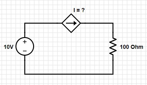
I = V / R
I = 10 V / 100 Ω
I = 0.1 A
So, in this example, the current flowing through the 100-ohm resistor is 0.1 amperes (100 mA).
Understanding these fundamental concepts of resistance, voltage, and current in a resistor is essential for analyzing and designing electronic circuits, as they dictate how components behave and interact within a circuit.
Resistor Color Code
Understanding Resistor Color Coding and How to Read Resistor Values.
Resistor color coding is a system used to indicate the resistance value and tolerance of a resistor. Resistors typically have color bands painted on their surface, and each band represents a specific digit or multiplier.
By reading the colors on the resistor, you can determine its resistance value. Here’s how to read resistor values using the color coding system:
- Identify the Color Bands: Look at the resistor and identify the colored bands on its body. Most resistors have either four or five bands. The bands are located close to one end of the resistor.
- Determine the First and Second Significant Digits: The first two bands represent the significant digits of the resistance value. Each color corresponds to a specific number, as follows:
![]()
For example, if the first band is red and the second band is green, the first two significant digits are 2 and 5, respectively.
- Determine the Multiplier (Third Band): The third band represents the multiplier or the number of zeros to be added to the significant digits. It determines the magnitude of the resistance value. Each color corresponds to a specific multiplier, as follows:
| Black | x1 (10^0) |
| Brown | x10 (10^1) |
| Red | x100 (10^2) |
| Orange | x1,000 (10^3) |
| Yellow | x10,000 (10^4) |
| Green | x100,000 (10^5) |
| Blue | x1,000,000 (10^6) |
| Violet/Purple | x10,000,000 (10^7) |
| Gray | x100,000,000 (10^8) |
| White | x1,000,000,000 (10^9) |
| Gold | Divide by 10 (10^-1) |
| Silver | Divide by 100 (10^-2) |
For example, if the third band is orange, the multiplier is 1,000.
- Determine the Tolerance (Fourth Band, Optional):
If the resistor has a fourth band, it represents the tolerance of the resistor. The tolerance is the maximum deviation allowed from the stated resistance value. Common tolerance values are:
- Gold: ±5%
- Silver: ±10%
- Brown: ±1%
- Red: ±2%
- Calculate the Resistance Value:
Using the information gathered from the color bands, combine the first two digits, and multiply them by the multiplier to get the resistance value in ohms. If there’s a fourth band, apply the tolerance to the calculated resistance value.
For example, if you have a resistor with the colors: Brown, Black, Orange, Gold, the resistance value would be 10 * 1,000 = 10 kOhms (10kΩ) with a tolerance of ±5%.

Remember that not all resistors may have a tolerance band. In such cases, the resistor is considered to have a standard tolerance of ±20%. Additionally, some high-precision resistors may have a fifth band, indicating the temperature coefficient of resistance.
By understanding the resistor color coding system, you can quickly determine a resistor’s resistance value and tolerance without relying on printed markings or datasheets.
Practical Examples of Deciphering Color-coded Resistors
Let’s go through a few practical examples of deciphering color-coded resistors using the resistor color-coding system:
Example 1: 4-Band Resistor Resistor Colors: Yellow, Violet, Red, Gold
- Identify the significant digits: Yellow (4) and Violet (7).
- Determine the multiplier: Red (x100) since it is the third band.
- Combine the significant digits: 47
- Multiply by the multiplier: 47 * 100 = 4,700 ohms (4.7kΩ).
- Determine the tolerance: Gold (±5%).
So, the resistor value is 4.7kΩ with a tolerance of ±5%.
Example 2: 5-Band Resistor Resistor Colors: Brown, Black, Black, Orange, Brown
- Identify the significant digits: Brown (1) and Black (0).
- Determine the multiplier: Black (x1) since it is the third band.
- Combine the significant digits: 10
- Multiply by the multiplier: 10 * 1 = 10 ohms (10Ω).
- Determine the tolerance: Orange (±3%).
So, the resistor value is 10Ω with a tolerance of ±3%.
Example 3: 4-Band Resistor Resistor Colors: Red, Yellow, Green, Silver
- Identify the significant digits: Red (2) and Yellow (4).
- Determine the multiplier: Green (x100,000) since it is the third band.
- Combine the significant digits: 24
- Multiply by the multiplier: 24 * 100,000 = 2,400,000 ohms (2.4MΩ).
- Determine the tolerance: Silver (±10%).
So, the resistor value is 2.4MΩ with a tolerance of ±10%.
Example 4: 5-Band Resistor Resistor Colors: Orange, Gray, Brown, Red, Gold
- Identify the significant digits: Orange (3), Gray (8), and Brown (1).
- Determine the multiplier: Red (x100) since it is the fourth band.
- Combine the significant digits: 38,1
- Multiply by the multiplier: 38,1 * 100 = 3,810 ohms (3.81kΩ).
- Determine the tolerance: Gold (±5%).
So, the resistor value is 3.81kΩ with a tolerance of ±5%.
Remember to double-check your results and ensure you interpret the colors accurately. The resistor color coding system is a handy way to quickly identify resistors’ resistance value and tolerance without relying on external references. It becomes easier with practice and familiarity with the color code.
Author Profile
- 20+ years embedded hardware design professional with a burning passion for teaching. Sharing the intricate world of embedded hardware is my mission and joy.
Latest entries
 Tech Updates30 November 2025STM32WBA6: The Next-Generation MCU Powering Secure Short-Range Wireless Designs
 Blogs24 November 2025High-Speed PCB Layout Design Guide-104
 Tech Updates14 September 2025Renesas Launches RL78/L23 Ultra-Low-Power MCUs to Power Smarter Home Appliances
 Blogs7 September 2025High-Speed PCB Layout Design Guide-103


