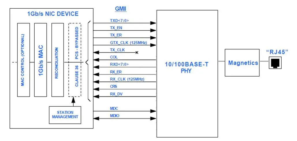
The Gigabit Media Independent Interface (GMII), specified by IEEE Std 802.3 Clause 35, is a standard interface designed to facilitate a simple and standardized connection between the Media Access Control (MAC) layer and Physical Layer (PHY) devices in Gigabit Ethernet applications, supporting data rates up to 1 Gbps.
Utilizing 24 signal lines and operating at a clock frequency of 125 MHz, GMII abstracts physical media details, ensuring interoperability between different manufacturers’ devices and extending the capabilities of the original Media Independent Interface (MII).
Widely adopted in network interface cards, switches, routers, and other networking equipment, GMII enables versatile and efficient network designs. Gigabit Ethernet MAC functions internally, uses GMII to connect to external PHY devices, thereby supporting high-speed networking and ensuring compatibility with various PHY devices.
The Gigabit Media Independent Interface (GMII) provides an 8-bit wide datapath between a 1000 Mbit/s PHY and a MAC sublayer, supporting high-speed data transfer in Gigabit Ethernet applications. Additionally, GMII is compatible with the 4-bit wide Media Independent Interface (MII) as defined in the IEEE 802.3z specification, ensuring it also supports the IEEE 802.3u Clause 22.4 MII standard for interoperability with various network devices.
Gigabit Media Independent Interface (GMII) Block- Diagram
The Gigabit Media Independent Interface (GMII) supports speeds up to 1 Gbps with a clock rate of 125 MHz. It is fully backward-compatible with the MII specification. Signal descriptions are provided in Table below.
Gigabit Media Independent Interface (GMII) Signal Descriptions
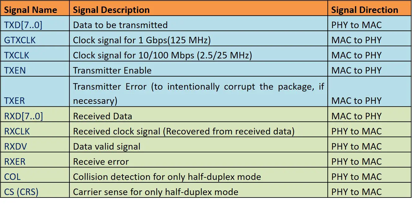
Brief Description of the Functionality of GMII signals
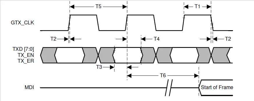
GTX_CLK:- GTX_CLK provides the timing reference for the transfer of the TX_EN, TX_ER and TXD. It’s supplied by the MAC device. Its frequency is nominally 125 MHz. This clock can be stopped when the device is in 10/100BASE-T modes, and also during Auto-Negotiation
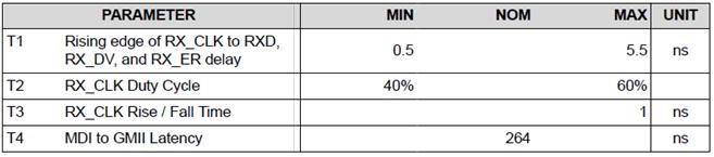
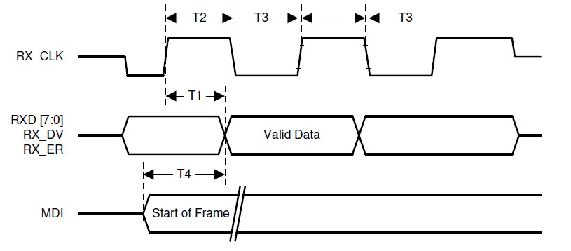
RX_CLK:- RX_CLK is the timing reference for the transfer of the RX_DV, RX_ER and RXD signals. The PHY usually recovers this clock from the receive data from the physical medium and provides it to the MAC. This clock is derived from the local clock (e.g. GTX_CLK) if the physical medium is not attached. Its frequency is also nominally 125 MHz
TX_EN (Transmit Enable):- This signal is used to indicate to the PHY that data is present on the GMII for transmission. It is asserted synchronously with GTX_CLK from first octet of the preamble and remains asserted for the duration of the entire data frame.
TXD(7:0) (Transmit Data):- This signals are the 8 data signals that are used for the MAC to supply byte aligned data to the PHY for transmission.
TX_ER (Transmit Coding Error):- This signal is used to tell the PHY to transmit an illegal symbol code to the physical medium.
RX_DV (Receive Data Valid):- This signal is driven by the PHY to indicate the PHY is presenting recovered and decoded data on the RXD(7:0). It’s asserted during the entire data frame, and so provide an envelope signal for a valid data frame including Preambles, Start Frame Delimiter (SFD) and Frame Check Sequence (FCS) bytes. The MAC uses this signal to delineate the frame.
RXD(7:0) (Receive Data):- This signal are the 8 data signals for the PHY to present byte-aligned receive data to the MAC. Data byte on these signals is valid only when the RX_DV is asserted and RX_ER is de-asserted.
RX_ER (Receive Error) :- This signal is used by the PHY to indicate detection of illegal symbol code during a reception of a frame (when RX_DV is asserted), so the MAC can discard the frame. It’s used to signal Carrier Extension when RX_DV is de-asserted.
CRS (Carrier Sense) :- This signal is a signal driven by the PHY. While operating in half duplex mode, the PHY will assert CRS when either transmit or receive medium is non-idle and de-assert it when both transmit and receive media are idle. While operating in full duplex mode, the behavior is the CRS is not specified by the standard, hence it can be ignored by the MAC.
COL (Collision Detected):- This signal is asserted by the PHY upon detection of a collision on the medium when it’s operating in half duplex mode. While operating in full duplex mode, the behavior is the COL is not specified by the standard, hence it can be ignored by the MAC.
The valid code combinations for TXD(7:0), TX_EN, and TX_ER are defined in below table.
|
TX_EN |
TX_ER |
TXD(7:0) |
Description |
|
0 |
0 |
0x00 through 0xFF |
Normal inter-frame |
|
0 |
1 |
0x00 through 0x0E |
Reserved |
|
0 |
1 |
0x0F |
Carrier Extend |
|
0 |
1 |
0x10 through 0x1E |
Reserved |
|
0 |
1 |
0x1F |
Carrier Extend Error |
|
0 |
1 |
0x20 through 0xFF |
Reserved |
|
1 |
0 |
0x00 through 0xFF |
Normal data transmission |
|
1 |
1 |
0x00 through 0xFF |
Transmit error propagation |
The valid code combinations for RXD(7:0), RX_DV and RX_ER are defined in below table.
|
RX_DV |
RX_ER |
RXD(7:0) |
Description |
|
0 |
0 |
0x00 through 0xFF |
Normal inter-frame |
|
0 |
1 |
0x00 |
Normal inter-frame |
|
0 |
1 |
0x01 through 0x0D |
Reserved |
|
0 |
1 |
0X0E |
False Carrier indication |
|
0 |
1 |
0x0F |
Carrier Extend |
|
0 |
1 |
0x10 through 0x1E |
Reserved |
|
0 |
1 |
0x1F |
Carrier Extend Error |
|
0 |
1 |
0x20 through 0xFF |
Reserved |
|
1 |
0 |
0x00 through 0xFF |
Normal data reception |
|
1 |
1 |
0x00 through 0xFF |
Data reception error |
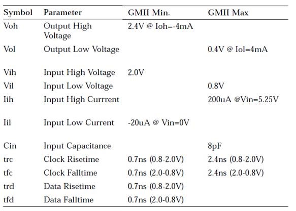
GMII Electrical Characteristics
- GMII electrical specifications align with MII specifications in:
- Input and output buffer strengths. GMII typically uses LVDS (Low Voltage Differential Signaling) for data transmission.
- I/Obuffer strengths are designed to be compatible with LVDS levels, typically operating at around 1.2 to 1.5 volts.
- Compatibility with 5V and 3.3V supply voltages.
- Integration of G-10b interface specifications contributes to GMII’s DC and AC characteristics.
- Electrical signaling interoperability among MII, GMII, and G-10b interfaces.
- All interfaces use TTL levels for sampling.
- MII receivers must tolerate input potentials from OV to +5.5V and handle transients from -1.8V to +7.3V over a duration of 15ns.
GMII DC Specification
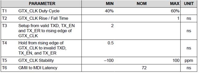
GMII Clock and Signal Timing
A GMII PHY device requires a 125 MHz clock for the timing reference for the TX signals, and the MAC provides this clock on the GTX_CLK Pin. This clock source is supplied to each cluster to provide individual transmit reference clock for each GMII interface.
On the RX side, the MAC expects the PHY to supply the 125 MHz clock reference for the RXD, RX_ER, and RX_DV signals. This clock signal is output on the RCLK pin, which the MAC uses to latch the incoming signals.
GMII Transmit Timing
GMII Receive Timing
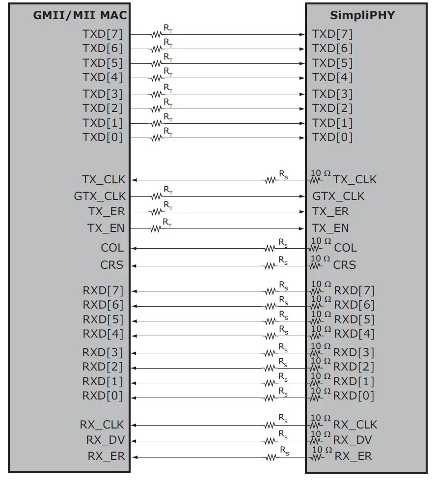
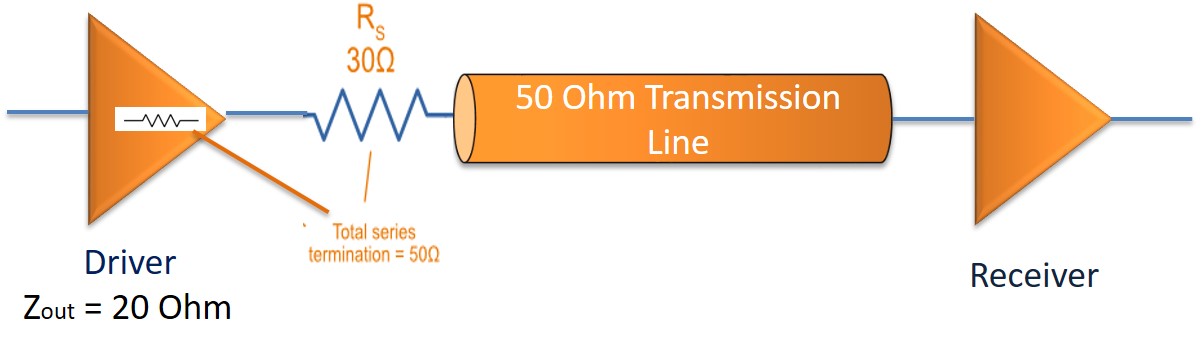
Signal Termination
GMII signals will be source-terminated to preserve signal integrity. Please refer below block diagram, where the placement of the series termination resistance is shown.
Equations:-
Rd (Buffer Impedance) + Rs (Source Termination Impedance = ZO (Transmission Line Impedance) Gigabit Media Independent Interface (GMII).
Below picture shows an example of series termination on GMII signals.
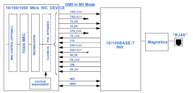
Switching Ethernet PHY from GMIl to MII
When the PHY device determines during the Auto-Negotiation process that it needs to run at 10 or 100 Mb/s speed, it will switch to the MII type of interface. MII is also specified in the IEEE 802.3 standard. The difference between MII and GMII is that the TX and RX data buses are 4 bits wide in MII, and the TX clock is output from the PHY device. The block diagram below depicts seamless switching of Ethernet PHY from GMII mode to MII mode.
Summary
The Gigabit Media Independent Interface (GMII) is a standard interface specified by IEEE Std 802.3 Clause 35, facilitating connections between the Media Access Control (MAC) layer and Physical Layer (PHY) devices in Gigabit Ethernet applications. Key features and functionalities of GMII include:
- Data Transfer: Supports data rates up to 1 Gbps through an 8-bit wide datapath.
- Clocking: Operates at a clock frequency of 125 MHz for high-speed data transmission.
- Backward Compatibility: Compatible with the 4-bit wide Media Independent Interface (MII), ensuring interoperability with various network devices.
- Signal Descriptions: Includes various signals such as TXD, GTXCLK, TXCLK, TXEN, TXER, RXD, RXCLK, RXDV, RXER, COL, and CRS, each serving specific functions in data transmission and error detection.
- Electrical Characteristics: Aligns with MII specifications, utilizing LVDS for data transmission and supporting 5V and 3.3V supply voltages.
- Clock and Signal Timing: Requires a 125 MHz clock for transmission timing and expects the PHY to provide the clock for reception.
- Signal Termination: Utilizes source termination to preserve signal integrity, ensuring reliable data transmission.
- Switching from GMII to MII: During Auto-Negotiation, the PHY device can seamlessly switch from GMII to MII interface if needed, with MII featuring a 4-bit wide data bus.
Author Profile
- 20+ years embedded hardware design professional with a burning passion for teaching. Sharing the intricate world of embedded hardware is my mission and joy.
Latest entries
 Tech Updates30 November 2025STM32WBA6: The Next-Generation MCU Powering Secure Short-Range Wireless Designs
 Blogs24 November 2025High-Speed PCB Layout Design Guide-104
 Tech Updates14 September 2025Renesas Launches RL78/L23 Ultra-Low-Power MCUs to Power Smarter Home Appliances
 Blogs7 September 2025High-Speed PCB Layout Design Guide-103


