In power supply circuits, ripple factor is a critical parameter because it affects the stability and quality of the DC output. Excessive ripple can lead to voltage variations that are unsuitable for sensitive electronic devices and can result in performance issues or damage over time. Therefore, minimizing ripple through proper filtering and regulation techniques is essential in power supply design to ensure the reliable operation of electronic systems
What is Ripple?
Ripple in an electronic circuit refers to the residual AC component present in a DC voltage or current. It’s typically expressed as the peak-to-peak voltage or current as a percentage of the nominal DC output.
This residual AC component often stems from imperfect filtering or regulation in power supplies or signal processing circuits.These ripples are superimposed on the DC signal and occur at the frequency of the AC mains or the switching frequency of the switching regulator.
Voltage Ripple
Voltage ripple is the fluctuation in the output DC voltage of a power supply or circuit. It is usually measured as the peak-to-peak voltage or as a percentage of the average voltage.
In a basic rectifier circuit, AC voltage from the mains is converted into pulsating DC. In a half-wave rectifier, only one half of the AC waveform is utilized, resulting in a significant amount of ripple. Full-wave rectifiers, such as bridge rectifiers, utilize both halves of the AC waveform, which reduces ripple compared to half-wave rectifiers but doesn’t eliminate it entirely.
To reduce ripple, a smoothing capacitor is often connected across the output of the rectifier. During the peak of the AC cycle, the capacitor charges up, and during the trough, it discharges, supplying current to the load. However, capacitor cannot fully eliminate the ripple, especially at higher frequencies or under varying load conditions. Therefore a minimal amplitude (less than 100mV) of ripple always present in the DC output voltage and that is acceptable in mostly power supply designs.
Changes in the load connected to the rectifier circuit can also contribute to voltage ripple. When the load current increases or decreases, it affects the discharge rate of the smoothing capacitor, causing ripple in the output voltage.
Current Ripple
Current ripple refers to the variation in the output current of a circuit or power supply. In switching regulators and switch-mode power supplies (SMPS), current ripple is primarily generated due to the operation of the inductor in conjunction with the switching action of the power semiconductor devices (usually MOSFETs).
In SMPS or switching regulators, during the ON state of the switching transistor (MOSFET), energy from the input source is stored in the inductor in the form of a magnetic field.
When the transistor switches OFF, the magnetic field collapses, and the stored energy is transferred to the output load and the output capacitor. The rate at which energy is transferred to the output largely depends on the inductance value. Higher inductance results in slower energy transfer, reducing current ripple but potentially increasing the physical size and cost of the inductor.
Current ripple in a switching regulator is directly related to the rate of change of inductor current during each switching cycle. Higher inductor values result in lower current ripple because they can store more energy for a given change in current.
Inductor current ripple () is typically calculated using the formula:
(1) 
Where:
- is the output voltage.
- is the duty cycle of the switching transistor.
- is the switching frequency.
- is the inductance
Typically, the current ripple of an inductor is designed to be approximately 30% of the average inductor current as a general guideline.
The combination of an inductor (in series) and capacitor (in parallel) forms a low-pass filter. This filter is designed with a low corner frequency to attenuate the ripple in DC output. Increasing the inductance reduces the necessary capacitance to achieve the desired output voltage ripple. However, excessively large inductance can result in increased size and cost, while insufficient inductance requires a larger output capacitor. Finding the optimal balance between these factors is a matter of design trade-offs.
Ripple Voltage Waveform of Full Wave Rectifier
The circuit depicted below is a center-tapped full-wave rectifier configuration. It operates by receiving 230VAC input on the transformer’s primary side and delivers rectified DC output voltage across the load resistor R1. Additionally, a 10uF capacitor C1 is connected in parallel with the load resistor to mitigate the ripple present in the output DC voltage.
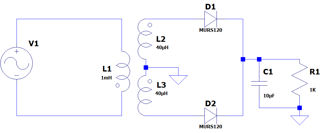
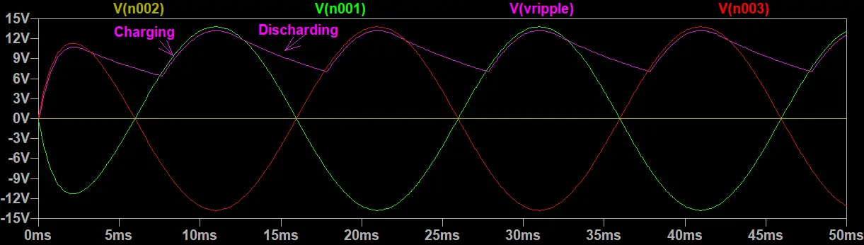
In the provided waveform, the pink waveform labeled “Vripple” depicts the smoothed ripple waveform, illustrating the processes of charging and discharging of the capacitor.
Define Ripple Factor
The ripple factor is a measure used to quantify the amount of ripple present in a rectified DC voltage or current waveform.
In other words,
The ripple factor defined as a quantitative measure to assess the extent of ripple, or fluctuation, within a rectified direct current (DC) voltage or current waveform.
The ripple factor provides a numerical representation of the magnitude of this ripple relative to the average value of the DC component. By comparing the root mean square (RMS) value of the AC component (ripple) to the average value of the DC component, the ripple factor offers insights into the quality and stability of the rectified DC output.
A lower ripple factor indicates a smoother and more stable DC output, while a higher ripple factor indicates a greater amount of ripple present in the output. Minimizing the ripple factor is crucial in power supply design to ensure the reliability and performance of electronic circuits, especially in applications where precise and stable DC voltage or current is required.
Ripple Factor Formula
The ripple factor is typically defined as the ratio of the root mean square (RMS) value of the AC component (ripple voltage or current) to the average value of the DC component.
Mathematically, the ripple factor (γ) can be calculated using the formula:
(2) 
RMS value of the AC component [Vr(rms)]: This represents the effective value of the AC voltage or current present in the waveform.
Average value of the DC component (VDC): This is the mean value of the DC voltage or current. For a rectified waveform, it’s usually the average value over one cycle of the waveform.
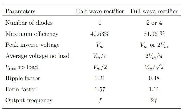
A Comparison of Different Parameters of Half-Wave and Full-Wave Rectifiers
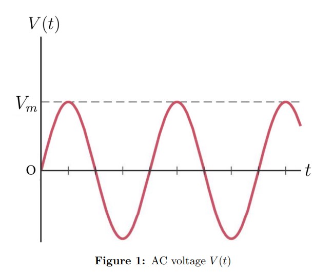
AC Voltage Waveform Representation
Calculating the Ripple Factor of Half Wave Rectifier
- RMS Value of AC Component (Vr(rms)): In a half-wave rectifier, Vr(rms)is the root mean square value of the ac-component of rectified output voltage.
(3) 
- Average Value of Output DC Component (VDC): For a half-wave rectified waveform, the average DC output value is calculated as.
(4) 
Where Vm is the Peak voltage of the AC input voltage.
- Ripple Factor (γ):
Using the formula in equation 1,
(5) 
(6) 
(7) 
For half wave rectifier
(8) 
Therefore, ripple factor for half wave rectifier can be calculated as
(9) 
(10) 
(11) 
Calculating the Ripple Factor of Full Wave Rectifier
Using the formula of ripple factor from equation 1
(12) 
For full wave rectifier Vrms can be defined as
(13) 
Also for full wave rectifiers Average output voltage VDC can be defined as
(14) 
Therefore, ripple factor for full wave rectifier can be calculated as
(15) 
(16) 
(17) 
How to Reduce Ripple?
To reduce ripple in a circuit, smoothing capacitors are commonly employed. These capacitors help convert the ripple voltage into a smoother DC voltage. Aluminum electrolytic capacitors are frequently utilized for this purpose due to their high capacitance values, typically 100uF or greater.
The ripple voltage (Vripple) is the peak-to-peak voltage of the output waveform and can be calculated using the formula:
(18) 
Where
Vm is the Peak Voltage of AC input
f is the AC input frequency
RL is the load resistor
“A typical acceptable level of ripple voltage is around 100mV peak-to-peak.”
Most high-quality power supplies boast ripple and noise specifications better than 10mV RMS, with Switched-Mode Power Supplies (SMPS) achieving figures of 50mV or lower. Nonetheless, for higher current supplies, slightly elevated values might be expected.
Author Profile
- 20+ years embedded hardware design professional with a burning passion for teaching. Sharing the intricate world of embedded hardware is my mission and joy.
Latest entries
 Tech Updates30 November 2025STM32WBA6: The Next-Generation MCU Powering Secure Short-Range Wireless Designs
 Blogs24 November 2025High-Speed PCB Layout Design Guide-104
 Tech Updates14 September 2025Renesas Launches RL78/L23 Ultra-Low-Power MCUs to Power Smarter Home Appliances
 Blogs7 September 2025High-Speed PCB Layout Design Guide-103


