A full wave rectifier is an electronic circuit used to convert alternating current (AC) into pulsating direct current (DC). Unlike a half-wave rectifier which only utilizes half of the input waveform, a full-wave rectifier takes advantage of both the positive and negative halves of the AC input signal.
There are two main types of full-wave rectifiers:
- Center-Tapped Full Wave Rectifier
- Bridge Rectifier
In this blog, we will understand about center-tapped full wave rectifier.
Also Read – Half Wave Rectifier
Center-Tapped Full Wave Rectifier
This configuration uses a center-tapped transformer. Two diodes are connected to the ends of the secondary winding of the transformer, and the center tap is connected to the ground or reference potential. The AC input voltage is applied across the two ends of the secondary winding. When the input voltage is positive, one diode conducts and charges the load, and when the input voltage is negative, the other diode conducts to maintain the current flow in the same direction.
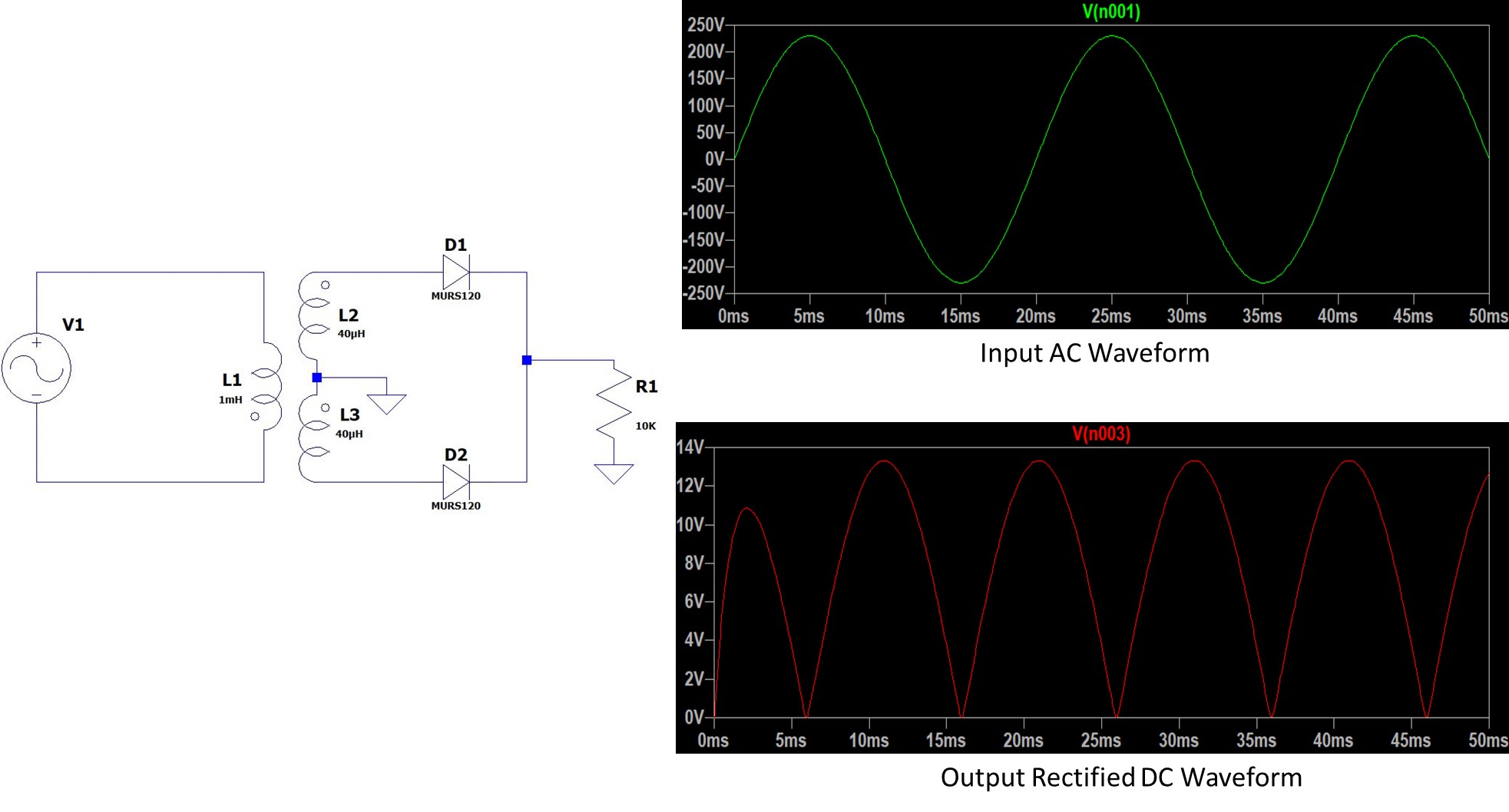
Center-Tapped Full Wave Rectifier Circuit Diagram
In this example circuit we have a center-tapped full-wave rectifier circuit where a 230VAC voltage is applied to the primary winding of the transformer. The transformer has a step-down ratio is 16:1, and the secondary winding is center-tapped.
Components of Center-Tapped Full Wave Rectifier
- Transformer: The primary component is a center-tapped transformer. A center tap is a connection made at the midpoint of the transformer winding. This configuration enables the rectification of both halves of the input AC cycle.
- Diodes: Two diodes are used in the circuit.
Working of Center-Tapped Full Wave Rectifier
AC Input
The AC input voltage is applied across the two ends of the transformer’s primary winding.
Transformer Action
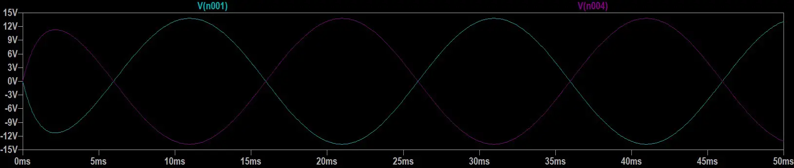
When the AC voltage is applied, it induces an alternating magnetic flux in the transformer core. Due to the center tap, the secondary winding of the transformer produces two separate output voltages with opposite polarities concerning the center tap. As one-half of the primary winding produces a positive voltage, the other half produces an equal but negative voltage. See the below waveform generated at the secondary Winding.
Diodes Rectification
During the positive half-cycle of the input AC voltage, the upper end of the secondary winding becomes positive relative to the center tap, forward-biasing one diode and reverse-biasing the other. The forward-biased diode conducts and allows current to flow through it.
Simultaneously, the lower end of the secondary winding becomes negative relative to the center tap, forward-biasing the second diode and reverse-biasing the first. The second diode conducts as well, allowing current to flow in the same direction through the load.
Thus, during the positive half-cycle, current flows through the load in the same direction, producing a positive output voltage across the load.
During the negative half-cycle of the input AC voltage, the roles of the diodes reverse. The upper diode becomes reverse-biased, while the lower diode becomes forward-biased, allowing current to flow through the load in the same direction as before. Consequently, a positive output voltage is maintained across the load.
Output Filtering
Despite rectification, the output voltage may still have some ripple due to the pulsating nature of the input. To smooth out this ripple, a filter capacitor can be connected across the load. This capacitor charges during the peaks of the rectified waveform and discharges during the troughs, effectively reducing the ripple and producing a smoother DC output voltage.
Center-Tapped Full Wave Rectifier Calculation Formulas
Average Output Voltage of Center-Tapped Full Wave Rectifier
To calculate the average output voltage of a center-tapped full-wave rectifier, we need to consider the voltage across the load during both the positive and negative half-cycles of the input AC voltage.
For a center-tapped full-wave rectifier, the average output voltage can be calculated using the formula:
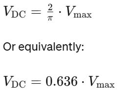
This formula holds true under ideal conditions, assuming no diode voltage drops or other losses. In practice, however, there will be some voltage drop across the diodes and some ripple in the output voltage due to the capacitive filter.
RMS Value of the Output Voltage of Center-Tapped Full Wave Rectifier
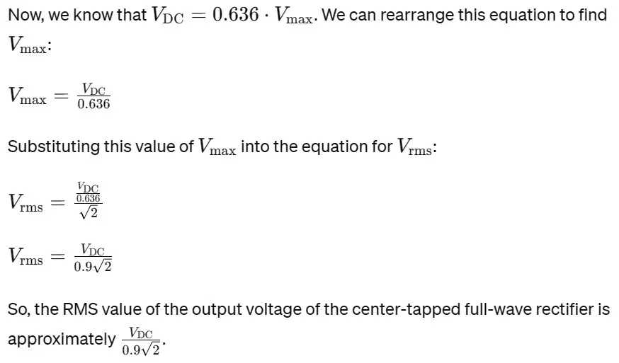
To calculate the RMS value of the output voltage of a center-tapped full-wave rectifier using Vmax (peak voltage of the rectified waveform) VDC (average DC output voltage across the load), we can use the following relationship:
For a full-wave rectifier, the output voltage waveform is a series of positive and negative half-cycles. Since the negative half-cycles are flipped to positive, we can consider the entire waveform to be positive for simplicity.
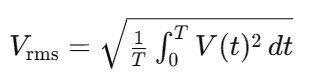
Given that Vmax is the peak voltage of the positive half-cycle and VDC is the average DC output voltage, we have:
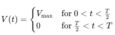
Where T is the period of the input AC waveform.
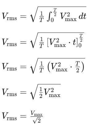
To find the RMS value, we need to integrate the square of this waveform over one complete cycle and then take the square root. Since the positive half-cycle contributes to the entire cycle, we can simplify the integration:
Ripple Factor of Center-Tapped Full Wave Rectifier
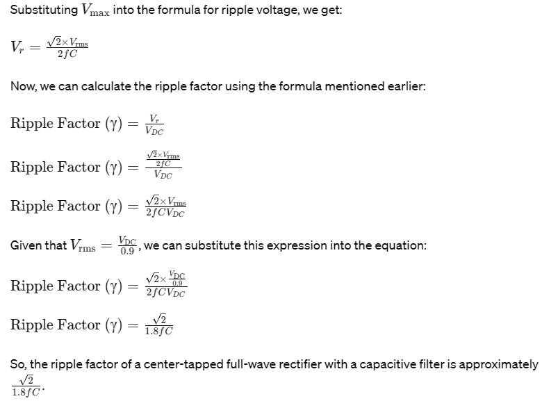
The ripple factor (γ) of a center-tapped full-wave rectifier represents the ratio of the root mean square (RMS) value of the ripple voltage (Vr) to the DC output voltage (VDC). The formula for calculating the ripple factor is as follows:
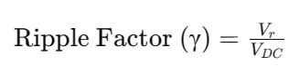
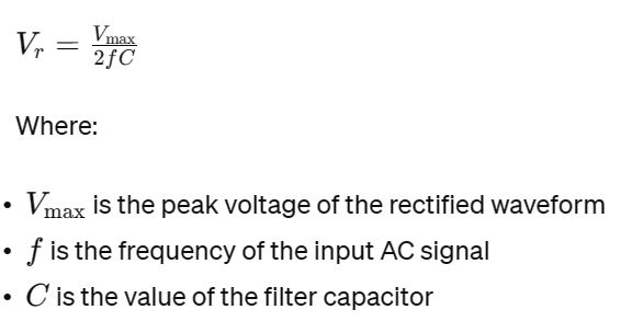
To compute the ripple voltage (Vr), we need to take into account the nature of the output waveform of the rectifier and the filtering applied. For a center-tapped full-wave rectifier with a capacitive filter, the ripple voltage (Vr) can be approximated using the following formula:
Efficiency of Center-Tapped Full Wave Rectifier
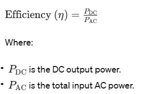
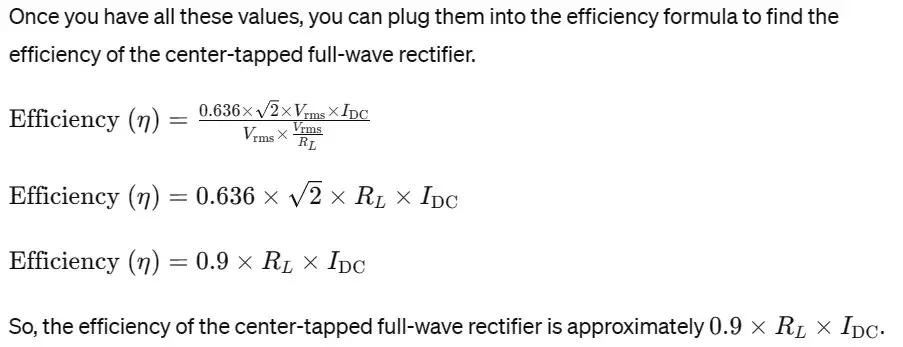
The efficiency (η) of a center-tapped full-wave rectifier is defined as the ratio of the DC output power to the total input AC power. Mathematically, it can be expressed as
To calculate the efficiency of the rectifier, we need to determine both the DC output power and the input AC power.
DC Output Power (PDC):
The DC output power can be calculated using the average output voltage (VDC) and the load current (IDC). It’s given by:
![]()
Total Input AC Power (PAC):
The total input AC power is the product of the RMS value of the input voltage (Vrms) and the input current (IAC). It’s given by:
![]()
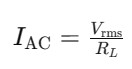
Input Current (IAC):
The input current can be calculated using Ohm’s Law. Assuming the load resistance (RL) is known, we can use the relationship:
Form Factor of Center-Tapped Full Wave Rectifier
The form factor of a center-tapped full-wave rectifier represents the ratio of the RMS (root mean square) value of the output voltage to its average value (DC voltage). It’s a measure of how “smooth” the output voltage waveform is. Mathematically, the form factor (F) is expressed as:
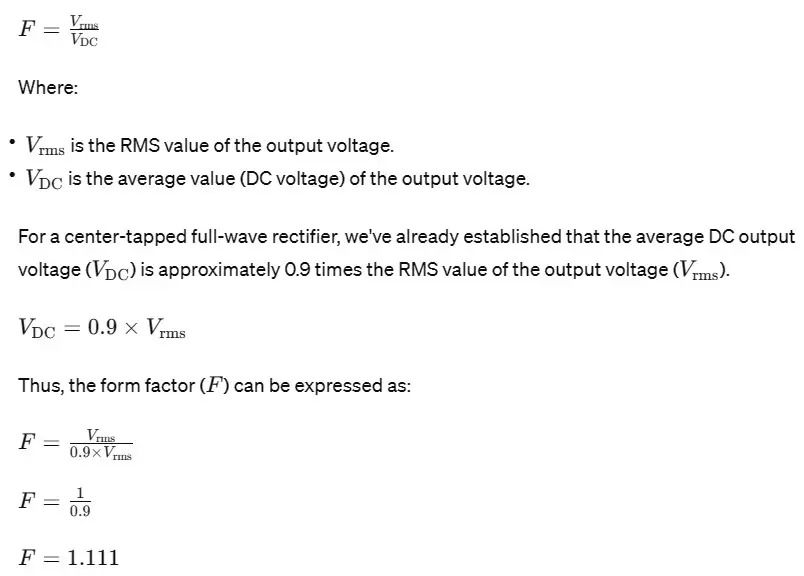
So, the form factor of a center-tapped full-wave rectifier is approximately 1.111. This indicates that the RMS value of the output voltage is about 1.111 times greater than its average value, reflecting a relatively smooth output waveform.
Advantages of Full Wave Rectifier
Full-wave rectifiers, including the center-tapped full-wave rectifier, offer several advantages over half-wave rectifiers:
- Efficiency: Full-wave rectifiers utilize both halves of the input AC waveform, resulting in a more efficient conversion of AC to DC compared to half-wave rectifiers, which only use one-half of the waveform.
- Higher Average Output Voltage: Full-wave rectifiers produce a higher average output voltage compared to half-wave rectifiers for the same input AC voltage and load resistance. This is because full-wave rectifiers rectify both positive and negative half-cycles of the input waveform, resulting in a higher DC output voltage.
- Smoothing Effect: Since full-wave rectifiers produce a pulsating DC output voltage with a higher frequency compared to half-wave rectifiers, the output voltage ripple is smaller. This facilitates easier filtering using capacitors, resulting in a smoother DC output voltage.
- Reduced Ripple Frequency: Full-wave rectifiers have a ripple frequency that is twice the frequency of the input AC waveform, while half-wave rectifiers have a ripple frequency equal to the frequency of the input AC waveform. A higher ripple frequency is advantageous as it enables the use of smaller filter capacitors for the same level of ripple reduction.
- Better Transformer Utilization: Full-wave rectifiers require a center-tapped transformer, which allows for better utilization of the transformer’s core compared to the single winding used in half-wave rectifiers. This leads to improved transformer efficiency and reduced cost and size.
- Improved Voltage Regulation: Full-wave rectifiers typically exhibit better voltage regulation compared to half-wave rectifiers. This is because any fluctuations in the input voltage are mitigated over both halves of the waveform, resulting in a more stable DC output voltage.
- Suitable for Three-Phase Systems: Full-wave rectifiers can be easily configured for three-phase input systems by using three-phase transformers and diode bridges. This makes them suitable for industrial applications where three-phase power is common.
Disadvantages of Half-Wave Rectifiers
While full-wave rectifiers offer several advantages over half-wave rectifiers, they also have some disadvantages:
- Complexity: Full-wave rectifiers, especially center-tapped designs, are more complex than half-wave rectifiers. They require a center-tapped transformer and two diodes, which increases the circuit complexity, component count, and cost.
- Higher Cost: The additional components required for full-wave rectifiers, such as the center-tapped transformer and additional diode, can increase the overall cost of the circuit compared to a half-wave rectifier.
- Transformer Requirement: Full-wave rectifiers require a center-tapped transformer, which can be bulkier and more expensive than the transformer required for a half-wave rectifier. This increases the size and weight of the overall circuit.
- Lower Peak Inverse Voltage (PIV): Full-wave rectifiers have a lower peak inverse voltage (PIV) rating for each diode compared to half-wave rectifiers. This is because the reverse voltage across each diode in a full-wave rectifier is only half of the peak input voltage, which may limit the range of applications in high-voltage scenarios.
- Higher Ripple Frequency: While full-wave rectifiers produce a smaller ripple compared to half-wave rectifiers, they have a ripple frequency that is twice the input AC frequency. This higher ripple frequency may require higher-frequency filtering components, adding complexity and cost to the circuit.
- Less Suitable for Low-Power Applications: In low-power applications where simplicity and cost-effectiveness are prioritized over efficiency and smoothness of the output voltage, full-wave rectifiers may be over-engineered. In such cases, a half-wave rectifier may be more suitable.
Author Profile
- 20+ years embedded hardware design professional with a burning passion for teaching. Sharing the intricate world of embedded hardware is my mission and joy.
Latest entries
 Tech Updates30 November 2025STM32WBA6: The Next-Generation MCU Powering Secure Short-Range Wireless Designs
 Blogs24 November 2025High-Speed PCB Layout Design Guide-104
 Tech Updates14 September 2025Renesas Launches RL78/L23 Ultra-Low-Power MCUs to Power Smarter Home Appliances
 Blogs7 September 2025High-Speed PCB Layout Design Guide-103


