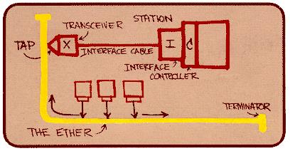
The diagram below was drawn by Dr. Robert M. Metcalfe in 1976 to present Ethernet to the National Computer Conference in June of that year. On the drawing are the original terms for describing Ethernet. Since then other terms have come into usage among Ethernet enthusiasts.
Ethernet is a widely utilized networking technology characterized by its asynchronous Carrier Sense Multiple Access with Collision Detect (CSMA/CD) protocol/interface. Operating at the data link layer, Ethernet employs packet-oriented transmission with a payload size typically ranging from 46 to 1500 bytes.
It utilizes statistical multiplexing, dynamically allocating network resources based on traffic load, to efficiently share the network medium among multiple users. This combination of features enables Ethernet to facilitate reliable and efficient data communication in various networking environments, making it suitable for modern networking infrastructure.
THEORY OF OPERATION
Ethernet is a data link and physical layer protocol defined by the IEEE 802.3 specification. It comes in many flavors, each defined by its maximum bit rate, transmission mode, and physical transmission medium.
- Maximum Bit Rate (Mbits/s): Ethernet standards support various maximum bit rates, including 10, 100, 1000 Mbits/s, and beyond.
- Mode of Transmission: Ethernet can operate in different modes of transmission, including broadband and baseband, depending on the specific standard and application requirements.
- Physical Transmission Medium: Ethernet networks can use various physical transmission media such as coaxial cables, fiber optics, and Unshielded Twisted Pair (UTP) cables, among others.
Ethernet Family Tree
Ethernet is defined in part by the physical medium over which frames are transmitted. The Ethernet family tree gives an overview about the class with the reference to the transport medium.
- 1 Mb/s
- 1Base5: 2 twisted telephone wire pairs
- 10 Mb/s
- 10Broad36: 1 broadband cable
- 10Base2: RG 58 coax cable
- 10Base5: 1 coax cable
- 10Base-F: 1 optical fiber
- 10Base-T: 2 pairs UTP CAT3 or better, full-duplex
- 100 Mb/s
- 100Base-FX: 2 optical fibers, Full-Duplex
- 100Base-T2: 2 pairs UTP CAT3 or better, full-duplex
- 100Base-T4: 4 pairs UTP CAT3 or better, half-duplex
- 100Base-TX: 2 pairs UTP CAT5 or better, full-duplex
- 1 Gb/s
- 1000Base-CX: Copper jumper cable
- 1000Base-LX: Long wavelength Multi/Single mode fiber
- 1000Base-SX: Short wavelength Multi mode fiber
- 1000Base-T: 4 CAT5e, CAT6 or better pairs
Note:-
- Unshielded Twisted Pair wire
- CAT3 wires and copper telephone wires are essentially interchangeable.
TCP/IP Model
Ethernet’s role can be best understood by looking at a protocol stack, which outlines a complete set of protocols in a layered approach. The OSI model, a standard reference model, defines how messages should be transmitted between any two points in a telecommunication network. The image below depicts the OSI and TCP/IP models positioned alongside each other, with the physical layer of the Ethernet protocol represented by a dotted line. Further elaboration on this will be provided in the forthcoming article.
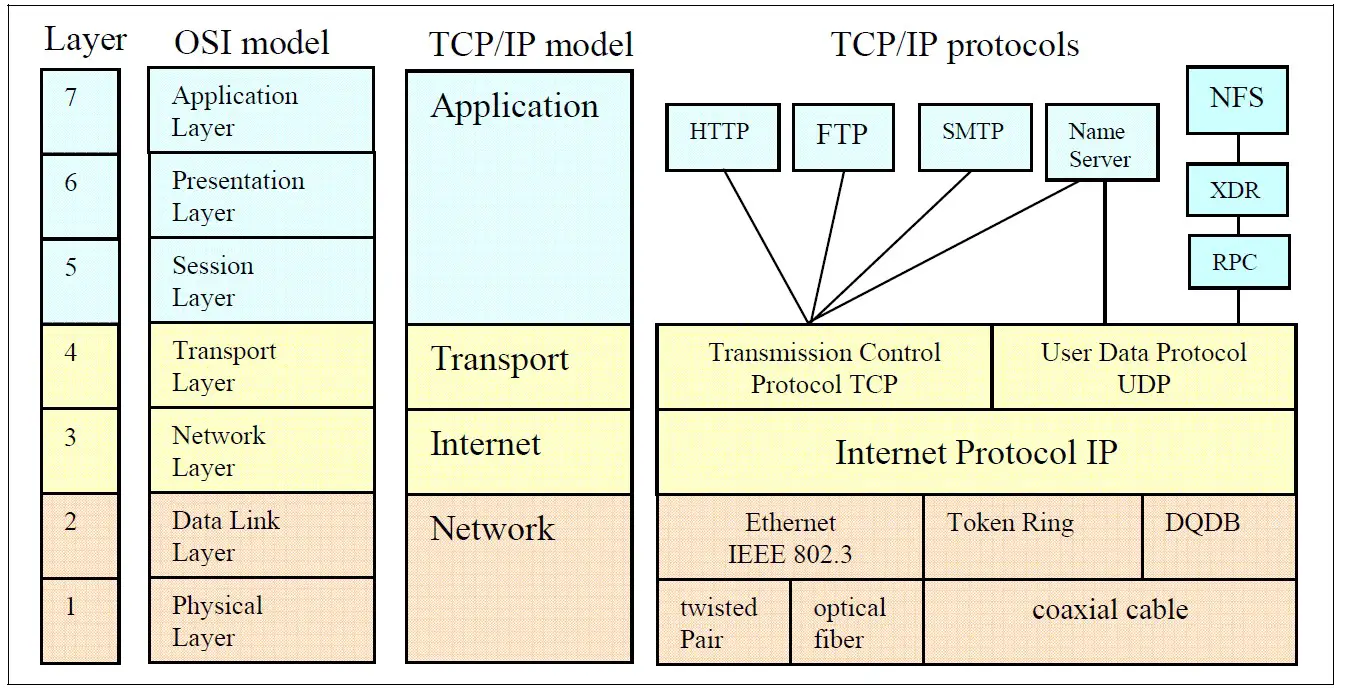
The TCP/IP layer specification & details are given in below table.
|
Layer |
Layer Name |
Layer Specification |
Layer Details |
|
|
5 |
Application |
Particular network applications |
The Application layer includes all available software implementations (e.g., FTP, HTTP, SMTP, DNS and others) that make up the lower layers. These applications can work only in combination with the API of TCP or UDP, which form the software implementation of the Transport layer. |
|
|
4 |
Transport |
Reliable data transport |
The Transport layer defines what should be done with the data. This layer is based on the following two popular protocols: UDP is a very simple protocol and is perfect for streaming sequences (e.g., audio or video). TCP is a highly reliable host-to-host protocol for a controlled connection. TCP is appropriate for applications that require guaranteed delivery. |
|
|
3 |
Internet |
Frame formatting and routing |
The Internet layer consists primarily of a software implementation. The IP header is evaluated or generated by software. |
|
|
2 |
Network |
Frame organization and
|
The network layer determines how messages are routed in a network, including QoS (Quality of Service) services, provision of network addresses for the transport layer, etc. |
|
|
1 |
Physical |
|
The Network layer combines the Data Link layer and Physical layer, including the twisted pair cable, the Physical layer device (PHY), and the Ethernet Media Access Controller (MAC). |
Ethernet Frames
Ethernet frames are often characterized as a packet delivery system. In actuality, an Ethernet frame comprises all the necessary components to meet the requirements and definition of a packet. An Ethernet frame consists of a header (Preamble to Length), payload (LLC to Pad), and a trailer (Frame Check Sequence), all bundled together in a specifically organized manner for transmission. Below table outlines the key components of an Ethernet frame, their descriptions, and the range of frame sizes. The frame size can vary depending on factors such as payload length and any additional headers or options included in the frame.
|
Data Width |
10/100 IEEE 802.3 Frame |
Frame Descriptions |
|
7 Byte |
Preamble |
These bits are used for synchronization and give each participant the time to observe the activity on the bus before the actual data arrives. |
|
1 Byte |
Start Frame Delimiter (SFD) |
Start of frame delimiter (10101011), the last byte of the preamble, indicates to the receiver that the actual data is on its way. |
|
6 Byte |
Destination Address (DA) |
Destination address. The destination MAC address field identifies the station or the stations that have to receive the message. This field takes 6 bytes of space. The destination address can be an individual, a multicast or a broadcast address. |
|
6 Byte |
Source Address (SA) |
Source address. The source MAC address field identifies the station from where the message originates. |
|
2 Byte |
Length (≤ 1500) |
For the field type, a distinction is drawn between Ethernet II (DIX standard) and the IEEE802.3 |
|
46 Byte |
Client Data (Payload) |
Data field contains the data to be sent. This data field is transparent- this means that the content of this field is completely free for Ethernet. Only the length has to be a minimum of 46 bytes and not more than 1500 bytes. |
|
Pad (if necessary) |
Padding bits are random data bits that, if necessary, can be added to the data in order to reach the minimum required 46 bytes. |
|
|
4 Byte |
Frame Check Sequence (FCS) |
Check sum is a 4-byte CRC value that the sender creates and sends. The receiver can check the integrity of the data with this code. |
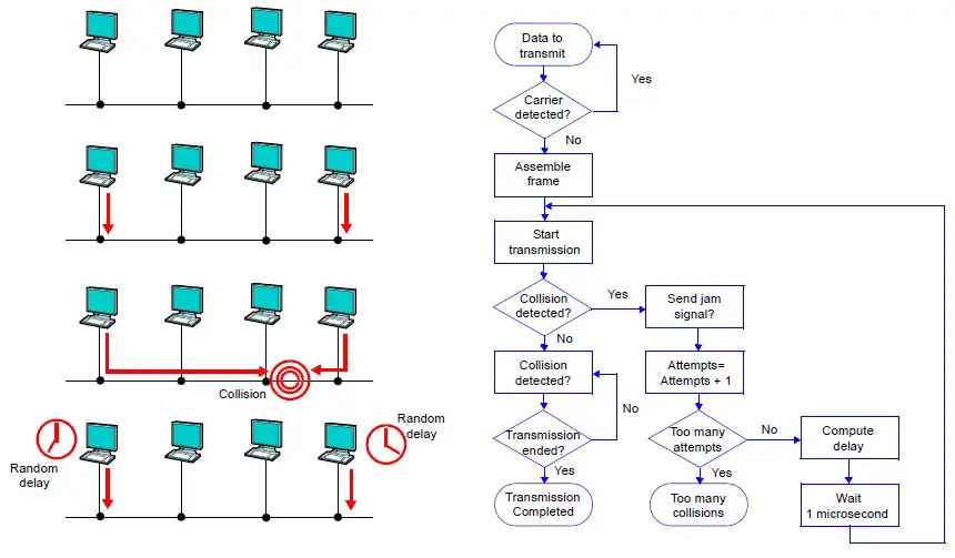
CSMA/CD
Ethernet was designed as a protocol to run over a shared medium, as shown in the figure below. In this topology, each node on the bus has equal access to the bus, but only one node may transmit at a time in Half Duplex Mode. Simultaneous transmission from multiple nodes would result in garbled data on the medium and subsequent loss of data. Carrier Sense Multiple Access with Collision Detection (CSMA/CD) is supported by the Physical Layer (PHY) and is required for networking in case of multiple accesses.
CS (carrier sense): – Each node must be able to detect when another node is transmitting. Carrier sense controls the line if there is traffic. If CS detects the line as free, data transfer can be started.
MA (multiple accesses):- Multiple nodes must be able to transmit on a shared medium If other devices started at the same time, MA is designed to yield a stable network. The Ethernet network was designed such that multiple accesses are normal.
CD (Collision detection): – A transmitting node must be able to determine when simultaneous transmission occurs in the case where multiple nodes see the medium as Idle and start transmitting at the same time. CD detects this multiple access, waits a time (random number), and gives the command to restart the procedure of a new data transfer.
Half Duplex
Half duplex is a mode of operation with CSMA/CD support of a local area network (LAN) in which Data Terminal Equipment (DTEs) contend for access to a shared medium. Multiple, simultaneous transmissions in a halfduplex mode CSMA/CD LAN result in interference, which requires resolution by the CSMA/CD access control protocol.
Full Duplex
Most of the modern Ethernet networks are configured in a point-to-point or a star topology. Full duplex operation is only possible if the shared transmission media is replaced by dedicated transmission media. Full duplex does not require CSMA/CD protocol. The different modes are described in these IEEE specifications:
- Half-Duplex: 10 MBit/s (IEEE 802.3)
- Full-Duplex: 100 MBit/s (IEEE 802.3u)
- Full-Duplex: Gigabit-Ethernet (IEEE 802.3ab) is Full-Duplex transfer with all four pairs
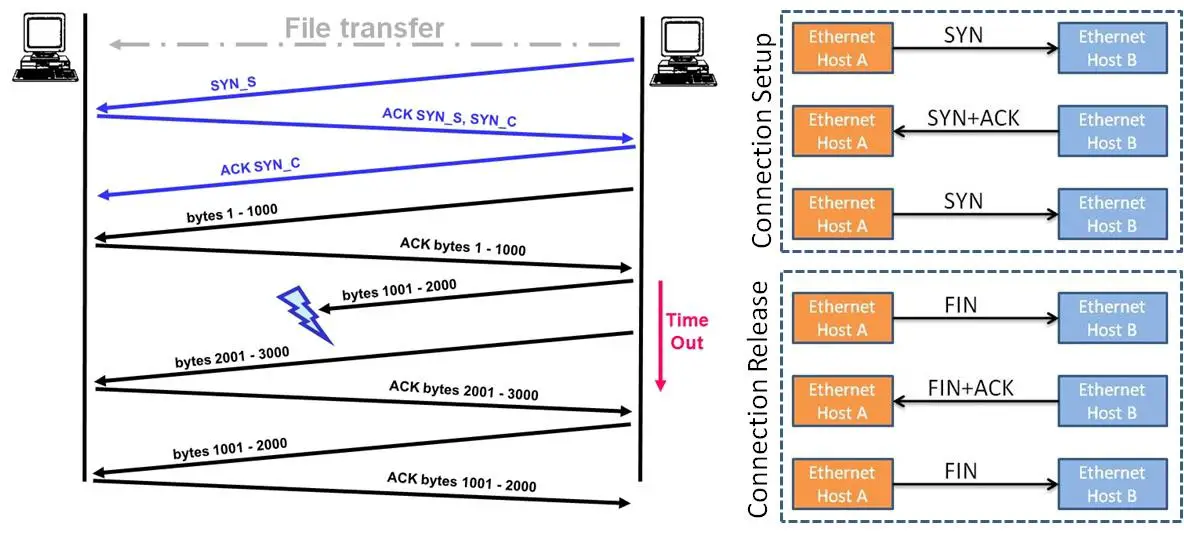
Ethernet Connection Setup & Release
The three-way handshake in TCP is a key process for establishing a reliable connection between two hosts. Below are the steps involved:
- Step 1 (Host A to Host B): Host A initiates the connection by sending a segment to Host B with the SYN (Synchronize) flag set to 1. This segment contains an Initial Sequence Number (ISN) that Host B will use for subsequent communication with Host A.
- Step 2 (Host B to Host A): Upon receiving the SYN segment from Host A, Host B responds by sending its own segment back to Host A. This segment has the SYN flag set to 1 to indicate synchronization and the ACK (Acknowledgment) flag set to 1 to acknowledge the receipt of Host A’s SYN segment. Host B also includes its own ISN in this segment.
- Step 3 (Host A to Host B): Finally, Host A acknowledges the receipt of Host B’s SYN segment by sending an ACK segment back to Host B. This segment has the ACK flag set to 1 and includes an acknowledgment number, which is one greater than the sequence number Host B sent in its SYN segment. This acknowledgment confirms the successful establishment of the connection.
After this three-way handshake is completed, both hosts are synchronized and ready to exchange data reliably over the established connection. This process ensures that both hosts agree on initial sequence numbers, synchronize their sequence number generation, and acknowledge each other’s agreement, thereby establishing a reliable connection.
“Connection release” in TCP also uses the three way handshake. Connection release uses the FIN in place of the SYN.
Summary
- Ethernet is a widely used networking technology defined by the IEEE 802.3 specification.
- It operates at the data link layer and uses the Carrier Sense Multiple Access with Collision Detect (CSMA/CD) protocol for shared medium access.
- Ethernet supports various maximum bit rates (10/100/1000 Mbps), modes of transmission (e.g., baseband, broadband), and physical transmission media (e.g., coaxial cables, fiber optics, UTP cables).
- Ethernet frames consist of a preamble, start frame delimiter, destination and source MAC addresses, length/type field, data payload, padding (if necessary), and a frame check sequence for error detection.
- CSMA/CD ensures fair access to the network medium by allowing nodes to detect carrier signals, contend for access, and detect collisions, facilitating reliable data transmission.
- Half-duplex mode is used for shared medium access, while full-duplex mode is employed in point-to-point or star topologies.
- The TCP/IP model provides a framework for understanding Ethernet’s role in network communication, encompassing layers for applications, transport, internet, and physical/network.
- The Ethernet family tree illustrates various Ethernet standards based on maximum bit rates and physical transmission media.
- Connection setup and release in Ethernet utilize a three-way handshake mechanism, involving SYN (synchronize) and ACK (acknowledge) segments exchanged between hosts to establish and terminate connections reliably.
Author Profile
- 20+ years embedded hardware design professional with a burning passion for teaching. Sharing the intricate world of embedded hardware is my mission and joy.
Latest entries
 Tech Updates30 November 2025STM32WBA6: The Next-Generation MCU Powering Secure Short-Range Wireless Designs
 Blogs24 November 2025High-Speed PCB Layout Design Guide-104
 Tech Updates14 September 2025Renesas Launches RL78/L23 Ultra-Low-Power MCUs to Power Smarter Home Appliances
 Blogs7 September 2025High-Speed PCB Layout Design Guide-103


