Half-wave rectifiers are considered the most fundamental and straightforward type of rectifiers. They represent the basic concept of rectification in its simplest form.
Due to their simpler design and lower efficiency, half-wave rectifiers are often used in low-power applications or where the complexity and cost of a full-wave rectifier cannot be justified.
Half Wave Rectifier and It’s Working
A half-wave rectifier is an electronic circuit used to convert alternating current (AC) into pulsating direct current (DC). It operates by allowing only one-half of the AC input waveform to pass through, effectively rectifying the signal.
A half wave rectifier consists of a single diode connected in series with the load resistor and the AC source.
During the positive half-cycle of the AC input voltage, the diode becomes forward-biased, allowing current to flow through it and the load resistor, resulting in a positive voltage across the load. However, during the negative half-cycle, the diode becomes reverse-biased, effectively blocking current flow and producing zero output voltage across the load.
This process results in the output waveform being a series of positive half-cycles with gaps during the negative half-cycles. The output voltage is therefore not continuous but rather pulsating, with a frequency equal to that of the input AC signal.
Half Wave Rectifier Circuit Diagram
To provide a clear understanding, let’s create visual representations of the AC input and pulsating DC output waveforms.
Let’s explore how it works, particularly with an input AC voltage of 24V peak-to-peak, using a 1N4148 diode, and a load resistor of 100 ohms.
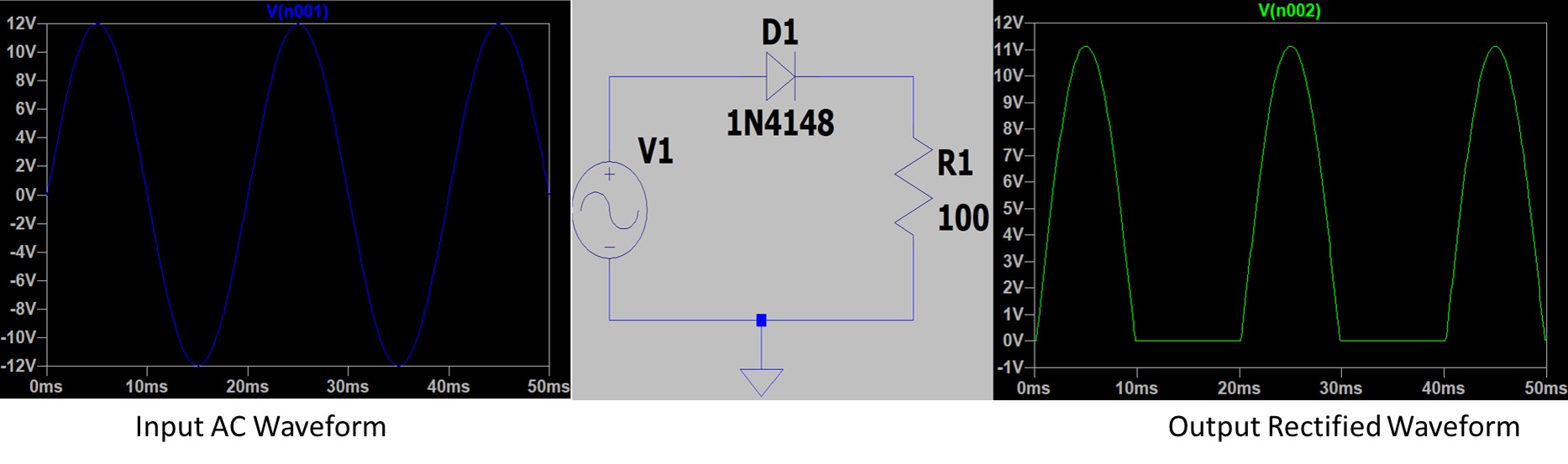
The input is an AC voltage of 24V peak-to-peak. This means the voltage varies from +12V to -12V (since the peak-to-peak voltage is double the peak voltage).
When the input AC voltage is positive, the diode D1 becomes forward-biased and conducts, allowing current to flow through the load resistor R1. When the input is negative, the diode is reverse-biased and blocks the current, preventing it from flowing.
In a half-wave rectifier, the output waveform will be a series of positive half-cycles corresponding to the positive half-cycles of the input AC signal. The negative half-cycles are blocked by the diode, so they do not appear in the output. This results in a pulsating DC waveform.
Half Wave Rectifier with Capacitor Filter
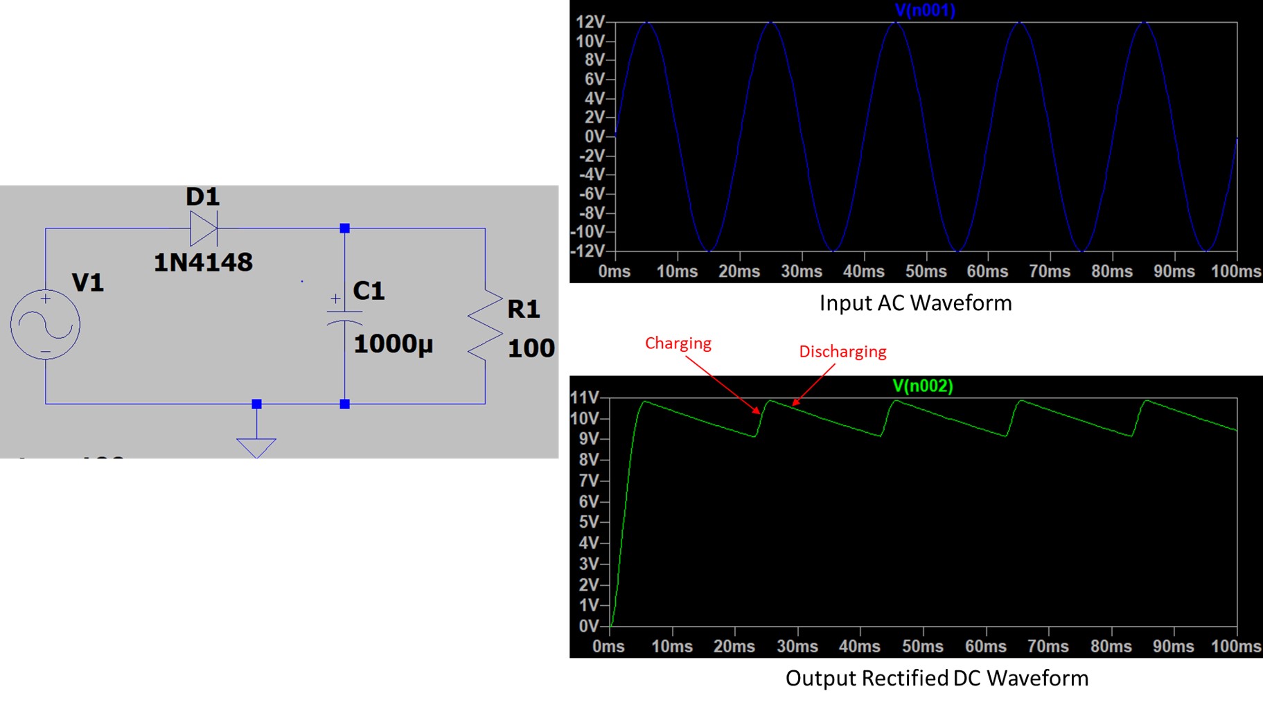
A half-wave rectifier with a capacitor filter is a simple circuit designed to convert AC power to DC power, with an added capacitor to improve the smoothness of the DC output. This type of rectifier allows only one-half of the AC waveform to pass, turning the AC input into a pulsed DC output. The capacitor then acts to smooth out these pulses.
Half Wave Rectifier with Capacitor Filter Circuit Diagram
 Components and Function
Diode: This allows current to flow only in one direction, effectively chopping off one half of the AC waveform.
Capacitor: Connected across the output, the capacitor charges up during the peak of the AC cycle and discharges (i.e., provides current) when the AC voltage drops below its peak. This process reduces the ripple in the output voltage.
Working Principle
When the AC input is on a positive half-cycle, the diode conducts, allowing current to flow through the load and charge the capacitor.
The capacitor charges up to the peak voltage minus the forward voltage drop across the diode.
During the negative half-cycle, the diode is reverse-biased and does not conduct. The capacitor starts to discharge through the load, providing a smoother DC output than a rectifier without a filter.
The time for which the capacitor can provide the current before the next charging cycle depends on the capacitance value and the load resistance.
Ripple Reduction
The capacitor filter significantly reduces the ripple in the output, but some ripple will still be present. The extent of ripple reduction depends on the capacitor’s size (measured in Farads) and the load resistance. Larger capacitors and higher load resistances result in smoother DC output with less ripple.
To calculate the capacitor value in a half-wave rectifier with a filter, you’ll need to consider the desired ripple voltage, the load current, and the frequency of the input AC voltage. Here’s a step-by-step guide to help you:
Calculate the Capacitor Value (C)
Use the following formula to calculate the required capacitance:
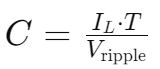
Where Load Current (IL) is the current that your load (the circuit you’re powering) requires.
Ripple Voltage (Vripple) is the AC component present in the rectified output. It depends on the application and the acceptable level of voltage variation.
![]() The charging time (T) of the capacitor is related to the time period of the AC input waveform. For a half-wave rectifier, it’s half the period of the input waveform.
The charging time (T) of the capacitor is related to the time period of the AC input waveform. For a half-wave rectifier, it’s half the period of the input waveform.
Limitation
While a half-wave rectifier with a capacitor filter is an improvement over a simple half-wave rectifier, it is less efficient and produces more ripple than a full-wave rectifier with a similar filter. This is because it only uses one half of the AC cycle, leading to a longer discharge time for the capacitor and, hence, a larger voltage drop before the capacitor is recharged.
Half Wave Rectifier Calculation Formulas
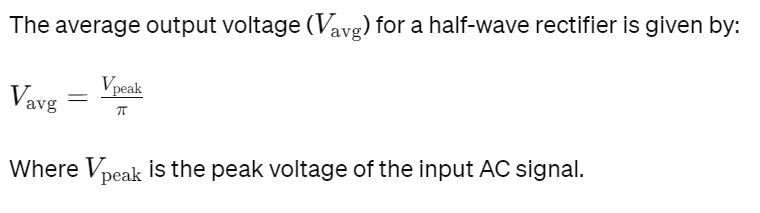
Average output voltage of a half wave rectifier
The average output voltage of a half-wave rectifier is calculated by considering only the positive half-cycles of the input AC waveform, as the negative half-cycles are blocked by the diode.
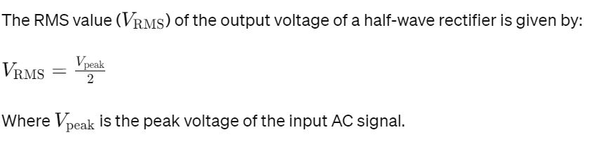
RMS value of the output voltage of a half wave rectifier
The root mean square (RMS) value of the output voltage of a half-wave rectifier can be calculated by considering the characteristics of the rectified output waveform. For a half-wave rectifier, only the positive half-cycles of the AC input are passed through.
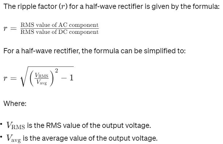
Ripple factor of half wave rectifier
The ripple factor of a rectifier circuit is a measure of the effectiveness of the rectification process. It quantifies how much of the AC component remains in the output, which is supposed to be DC. In simpler terms, it indicates the “smoothness” of the DC output.
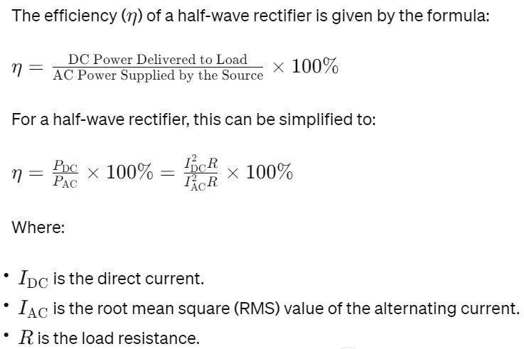
Efficiency of Half Wave Rectifier
The efficiency of a rectifier is a measure of how effectively it converts AC power into DC power. For a half-wave rectifier, the efficiency can be calculated based on the power delivered to the load versus the total power absorbed from the AC source.
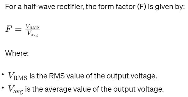
Form factor of Half Wave Rectifier
The form factor of a half wave rectifier is a measure of the shape of the output waveform. It’s defined as the ratio of the RMS (Root Mean Square) value to the average value (mean) of the output voltage or current.
Peak Inverse Voltage (PIV) of Half Wave Rectifier
The Peak Inverse Voltage (PIV) of a half wave rectifier is an important parameter, especially for the diode used in the rectifier circuit. PIV is the maximum voltage a diode can withstand in the reverse bias condition without breaking down.
In a half-wave rectifier, the diode is in reverse bias during the negative half-cycle of the AC input. Therefore, the PIV of the diode must be at least equal to the peak value of the AC input voltage to prevent breakdown.
For a half-wave rectifier, the PIV is equal to the peak voltage Vpeak of the input AC signal.
If the peak-to-peak voltage of the input AC signal is known, then the peak voltage Vpeak is half of this value. For example, if the input AC has a peak-to-peak voltage of 24V, then the PIV would be 12V.
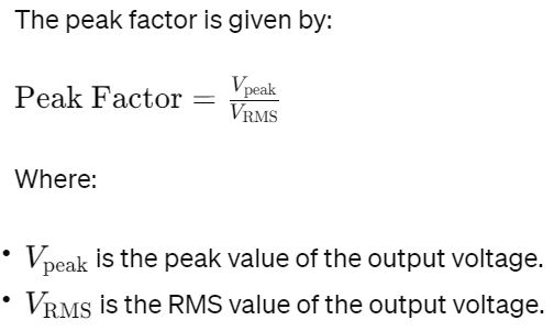
Peak factor of Half Wave Rectifier
The peak factor, also known as the crest factor of half wave rectifier, is a measure of a waveform that shows the ratio of the peak (maximum) value of the waveform to its RMS (Root Mean Square) value. For a half-wave rectifier, this factor can be calculated for the output voltage waveform.
Advantages of Half Wave Rectifier
Simplicity in Design
Half wave rectifiers have a minimalistic design, requiring only a single diode and a load resistor, making them easy to design and implement. This simplicity is beneficial for beginners and in applications where complex rectification is not necessary.
Cost and Time
The simplicity of the circuit translates into lower cost and shorter development time. This makes half-wave rectifiers an attractive option for budget-sensitive projects.
Reduced Component Count
The need for fewer components not only simplifies the design but also reduces the overall cost of the circuit. This includes savings on materials, assembly, and maintenance.
Budget-Friendly
In situations where cost is a significant consideration, such as in educational settings or basic consumer electronics, the cost-effectiveness of half-wave rectifiers is a major advantage.
Suitable for Specific Applications
The simplicity and cost-effectiveness of half wave rectifiers make them suitable for applications like small battery chargers, signal demodulation in communication systems, and other low-power requirements.
In low-power applications where efficiency and ripple are not primary concerns, half-wave rectifiers are an appropriate choice.
Disadvantages of Half Wave Rectifiers
Low Efficiency
Half-wave rectifiers use only one half of the AC waveform, leading to low efficiency as half of the input power is not utilized.
This inefficiency results in power wastage, making half-wave rectifiers unsuitable for high-power applications.
High Ripple Factor
Ripple factor is a measure of the fluctuations in the output DC voltage. Half-wave rectifiers exhibit a higher ripple factor because of the absence of the negative half-cycle of the input AC waveform.
The high ripple affects the smoothness of the DC output, leading to potential issues in sensitive electronic circuits.
Limited Use in High-Power Applications
The inherent inefficiency and high ripple factor make half-wave rectifiers unsuitable for high-power and precision applications.
In such cases, full-wave or bridge rectifiers are often considered as they offer higher efficiency and lower ripple.
Author Profile
- 20+ years embedded hardware design professional with a burning passion for teaching. Sharing the intricate world of embedded hardware is my mission and joy.
Latest entries
 Tech Updates30 November 2025STM32WBA6: The Next-Generation MCU Powering Secure Short-Range Wireless Designs
 Blogs24 November 2025High-Speed PCB Layout Design Guide-104
 Tech Updates14 September 2025Renesas Launches RL78/L23 Ultra-Low-Power MCUs to Power Smarter Home Appliances
 Blogs7 September 2025High-Speed PCB Layout Design Guide-103


