Transient Voltage Suppression (TVS) diodes are critical components used to protect sensitive electronic circuits from large transient spikes or voltage transients. These transients can be caused by electrostatic discharge (ESD), electrical fast transients (EFT), and lightning surges.
Although numerous components, both passive and active, can provide surge protection at a system input, the most commonly used solution is transient voltage suppression (TVS). TVS diodes are designed to dissipate fault energy by redirecting the surge current and clamping the surge voltage to a safe level.
The primary function of a TVS diode at a system input is to remain inactive during normal operation and then rapidly conduct and divert current to ground during a transient overvoltage, ensuring the system voltage remains at a safe, low level. However, in practice, TVS diodes exhibit non-ideal characteristics that must be carefully evaluated to provide effective protection without significantly impacting system performance.
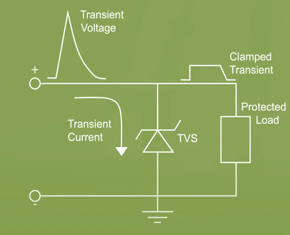
While TVS diodes are not without limitations, they are typically the most efficient solution for managing surge currents in the range of 2A to 250A. Their efficiency lies in their ability to respond extremely quickly to voltage spikes, typically within nanoseconds, making them ideal for protecting sensitive electronic circuits from transient events like electrostatic discharge (ESD), electrical fast transients (EFT), and lightning-induced surges
To ensure effective protection, selecting the right TVS diode for your application is essential. This guide provides a step-by-step approach to choosing the appropriate TVS diode, including compliance with IEC standards like IEC61000-4-2 (ESD), IEC61000-4-4 (EFT), and IEC61000-4-5 (Surge Protection).
Key Advantages of TVS Diodes for Surge Protection
- Fast Response Time: TVS diodes can clamp voltage spikes almost instantaneously (less than 1 ns), providing immediate protection to downstream components.
- Precise Clamping: They limit the overvoltage to a predefined clamping voltage, ensuring the surge does not exceed the safe operating voltage of the protected components. This makes them highly effective for precise applications where even slight voltage overshoot could damage sensitive electronics.
- Wide Current Range: TVS diodes can handle a broad range of surge currents, typically from as low as 2A up to 250A or more, depending on the specific diode selected. This versatility makes them suitable for a wide variety of applications, from small consumer electronics to industrial systems and automotive circuits.
- Low Standby Leakage: In their non-conducting state, TVS diodes draw minimal leakage current, ensuring they do not interfere with the normal operation of the circuit, making them ideal for energy-sensitive systems.
- Low Capacitance Options: For high-speed data lines or RF circuits, TVS diodes are available with low capacitance to ensure that they do not degrade signal integrity.
- Long life: Compared to other protection components like metal oxide varistors (MOVs) or gas discharge tubes (GDTs), TVS diodes offer a longer operational life due to their faster response time, minimal degradation over repeated transient events, and precise clamping characteristics, making them more reliable for long-term protection in sensitive electronic circuits.
Limitations of TVS Diodes
- Limited Power Dissipation: TVS diodes are excellent at handling short, high-energy transients but may not be suitable for prolonged or repetitive surge events without thermal degradation For very high-energy surges, such as direct lightning strikes, a TVS diode alone may not provide sufficient protection. In such cases, additional protection components (e.g., Gas Discharge Tubes or Metal Oxide Varistors) might be required to share the energy load.
Understand the Transient Threats
The first step in selecting a TVS diode is understanding the types of transient threats your circuit may face:
Electrostatic Discharge (ESD)
This is a short-duration high-voltage spike caused by static electricity. Compliance with IEC61000-4-2 is crucial for ESD protection. The standard defines test levels up to ±15 kV for air discharge and ±8 kV for contact discharge.
Select a TVS diode with low clamping voltage, high peak pulse power rating, and sufficient ESD withstand capability (±15 kV air and ±8 kV contact). Ensure that the diode is capable of clamping ESD pulses within the required time frame.
Electrical Fast Transients (EFT)
EFT pulses come from switching inductive loads, such as relays or motors. The IEC61000-4-4 standard specifies the test parameters for simulating EFT events. EFT events occur as bursts of fast spikes at lower energy levels than surges but can still damage components.
TVS diodes with higher clamping voltage and lower peak pulse current are generally used for EFT protection. EFT involves high-frequency transients, so low parasitic inductance in the diode packaging is important for fast transient clamping.
Surge Protection
High-energy surges, often caused by lightning strikes or power line disturbances, require robust protection. IEC61000-4-5 defines surge immunity testing, simulating waveforms with energies ranging from 500V to several KV.
Choose a TVS diode that can handle high peak pulse currents and higher clamping voltages. Consider the energy rating and the peak pulse power rating to ensure that the diode can absorb the energy without failure.
Define Key Parameters of TVS Diode
To ensure adequate protection, you must choose a TVS diode with appropriate electrical characteristics. Key parameters include:
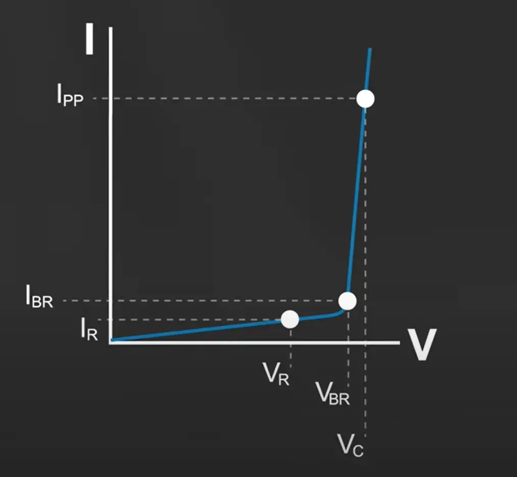
1- Reverse Stand-Off Voltage (VR)– This is the maximum continuous voltage the TVS diode can withstand without clamping. Choose a VR value that is 10-20% higher than the operating voltage of your circuit. At VR, the TVS diode leakage current IR is specified to be very low, generally less than 100nA.
2- Breakdown Voltage (VBR) – The breakdown voltage is where the TVS diode starts to conduct and clamp the transient. It must be higher than the operating voltage but low enough to activate during transients. At VBR the TVS diode will experience 1 mA of leakage current and start shunting current.
3- Clamping Voltage (VC) – This is the maximum voltage the TVS diode will allow across its terminals during a transient event. Ensure that the clamping voltage is lower than the damage threshold of your protected components.
4- Peak Pulse Current (IPP) – The peak pulse current rating indicates how much current the diode can handle during a surge.
5- Peak Pulse Power (PPPM): The maximum power that the diode can handle for a specified time duration (usually 10/1000 µs). It defines the energy capacity of the TVS diode during a transient event.
6- Capacitance – TVS diodes have parasitic capacitance(Ct), which can affect high-speed signals in communication lines or RF circuits. Low-capacitance diodes are crucial for applications requiring signal integrity. For interfaces running not more than 1MHz the TVS diode capacitance should not be more than 5pF and those interface running at 10GHz the TVS diode capacitance should not be more than 0.2pF.
7- Polarity: TVS diodes are available in both unidirectional and bidirectional configurations, with their differences evident in their I/V curves. Unidirectional TVS diodes feature a breakdown voltage slightly below 0 V in the negative direction, while bidirectional TVS diodes exhibit symmetrical breakdown voltages in both positive and negative directions.
This makes unidirectional TVS diodes suitable for signals that remain nominally positive. However, if a signal can swing into the negative range, a bidirectional TVS diode is necessary.
The tradeoff is that unidirectional TVS diodes offer a better negative clamping voltage (VCLAMP) due to their lower breakdown voltage (VBR), whereas bidirectional diodes do not. Be sure to consider the working range of your system when selecting the appropriate diode polarity.
Package and Mounting Considerations
TVS diodes come in a variety of packages, from small surface-mount devices (SMD) for compact designs to larger through-hole devices for higher power applications. The choice of package should match the power dissipation and space requirements of your design.
- Surface-Mount Devices (SMD) – Ideal for applications where space is constrained, such as mobile devices and portable electronics.
- Through-Hole Devices – Suitable for applications with higher power requirements, such as industrial and automotive electronics.
- Plastic package is flammability rated V-0 per UL-94.
Verify Environmental and Mechanical Specifications
In addition to electrical characteristics, make sure the TVS diode can withstand the environmental conditions of your application, such as:
- Temperature Ranges – Ensure the operating temperature range of the TVS diode covers the expected operating conditions of your circuit.
- Moisture Sensitivity – For high-humidity environments, choose diodes with proper moisture ratings.
Application Scenario
To choose a suitable TVS (Transient Voltage Suppression) diode for a 5V input signal line with a maximum IC pin tolerance of 10V, you need to evaluate several key parameters based on protection requirements outlined in standards like IEC61000-4-2 (ESD), IEC61000-4-4 (EFT), and IEC61000-4-5 (Surge). Here’s a step-by-step guide:
Step 1: Understand the Microcontroller’s Input Tolerance
- Maximum voltage tolerance: 10V
- Clamping voltage target: Must stay within the IC’s safe input range (< 10V).
- Signal voltage: Normal operating signal is 5V.
Step 2: Analyse the Protection Standards
- IEC61000-4-2 (Electrostatic Discharge – ESD)
- Defines protection against electrostatic discharge.
- Typical test levels: ±8 kV (contact discharge) and ±15 kV (air discharge).
- IEC61000-4-4 (Electrical Fast Transient – EFT)
- Specifies bursts of fast transients (e.g., from relay switches).
- Voltage level: 2–4 kV with a fast rise time (5 ns).
- IEC61000-4-5 (Surge Immunity)
- Addresses longer-duration surges caused by lightning or power disturbances.
- Voltage level: 1–4 kV, depending on the application.
Step 3: Select TVS Parameters
- Working Voltage (VR):
- This is the maximum operating voltage the TVS can handle continuously.
- For a 5V line, choose VR≥5V but close to this value for optimal performance.
- Example: VR = 5.3V.
- Breakdown Voltage (VBR):
- The voltage at which the TVS starts to conduct significantly.
- Should be slightly higher than VR to avoid interfering with the signal line.
- Example: VR≈6V.
- Clamping Voltage (VC):
- The voltage the TVS clamps to during a transient.
- Must be below the IC’s maximum pin tolerance (10V).
- Choose a TVS with VC≤10V during the expected transient.
- Peak Pulse Current (IPP):
- The maximum surge current the TVS can handle.
- Evaluate the transient levels based on IEC61000 standards:
- For IEC61000-4-2: Peaks of 30A (depending on the ESD gun setup).
- For IEC61000-4-4 and IEC61000-4-5: Higher currents, typically 20–50A.
- Choose IPP≥ expected transient current.
- Response Time:
- Should be fast (in nanoseconds) to protect against ESD and EFT.
Step 4: Example Calculation
Protection against IEC61000-4-2:
- VR=5.3V
- VBR=6V
- VC=7V (lower preferred)
- Peak current: ±30A
Protection against IEC61000-4-5:
- Surge voltage: 4 kV
- Using 42 Ω surge source impedance for signal line: Peak current = 4000/42=96A.
- Ensure TVS can handle peak current: IPP≥96A
Step 5: Search for TVS Diode
Look for a TVS diode meeting these parameters. Common options include:
- Part Numbers: SMAJ5.0A, SMBJ5.0A
Step 6: Verify Parameters in Datasheet
For the selected diode:
- Verify VR, VBR, VC, IPP.
- Check compliance with IEC61000 standards.
Step 7: Validate Design
After choosing the diode, test it under expected transient conditions to ensure it protects the IC’s pin effectively
Conclusion
Choosing the correct TVS diode involves a thorough understanding of your circuit’s operating environment and the types of transient threats it will face. By considering the key parameters like reverse stand-off voltage, clamping voltage, peak pulse current, and compliance with standards like IEC61000-4-2, IEC61000-4-4, and IEC61000-4-5, you can effectively safeguard your electronic circuits from damage due to transients.
Author Profile
- 20+ years embedded hardware design professional with a burning passion for teaching. Sharing the intricate world of embedded hardware is my mission and joy.
Latest entries
 Tech Updates30 November 2025STM32WBA6: The Next-Generation MCU Powering Secure Short-Range Wireless Designs
 Blogs24 November 2025High-Speed PCB Layout Design Guide-104
 Tech Updates14 September 2025Renesas Launches RL78/L23 Ultra-Low-Power MCUs to Power Smarter Home Appliances
 Blogs7 September 2025High-Speed PCB Layout Design Guide-103


