The USB On-The-Go (OTG) is a USB controller that can be auto-confabulated to host or device. This allows a USB controller to function as either a host or a device, depending on the status of the ID pin, enabling flexible connections without the need for a dedicated host device.
USB On-The-Go (OTG) is an addendum to the USB 2.0 specification that introduces a new class of devices designed for portable, battery-powered products with limited host capabilities. The USB OTG specification, fully compliant with the OTG Supplement to the USB 2.0 specification, supports data transfer rates across all USB speed modes: high-speed (480 Mbps), full-speed (12 Mbps), and low-speed (1.5 Mbps).
This makes it highly adaptable for a wide range of applications, including point-to-point connections (e.g., direct device connections without a hub) and multi-point applications.
As the name suggests, the primary goal of the OTG specification was to enable consumer portable devices to share data without requiring a computer. For example,Camera can connect directly to printers to print pictures, while MP3 players can exchange music files with each other and several others.
What is new in USB On-The-Go (OTG)?
The OTG specification introduces new cables, mini and micro connectors. connectors. A dual-role OTG device must use the micro-AB receptacle, which accepts either a micro-A plug or a micro-B plug’
The new connector includes an additional pin (ID):
- Left open on the micro-B plug
- Grounded in the micro-A plug to determine initial roles
OTG specification also introduces two new protocols: Session Request Protocol (SRP) and Host Negotiation Protocol (HNP). Additionally, it defines a new type of USB device, known as a “dual-role device,” which has both host and peripheral capabilities.
USB On-The-Go (OTG) Features
An USB On-The-Go device must include the following features and characteristics:
- Compliant with the OTG Supplement to the USB2.0 Specification
- A limited Host capability
- Full-speed operation as a peripheral (high-speed optional)
- Full-speed support as a host (low-speed and high-speed optional)
- Host Negotiation Protocol
- Session Request Protocol
- One, and only one Mini-AB receptacle
- Minimum 8 mA output on VBUS
- Support 9 channels in host mode
- 9 Device mode endpoints in addition to control endpoint 0, 4 in, 3 out and 2 IN/OUT
- Built-in one 1024×35 bits FIFO
- Internal DMA with scatter/gather function
- Supports packet-based, dynamic FIFO memory allocation for endpoints for flexible, efficient use of RAM
- Support dynamic FIFO sizing
- Means for communicating messages to the user
USB On-The-Go (OTG) Electrical Characteristics

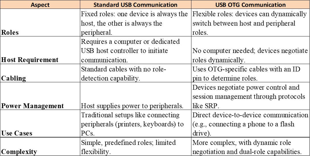
Differences between USB OTG and Standard USB Communication
USB OTG Cables & Connectors
The OTG supplement defines the following additional connectors:
- 5- Pin, Mini-A plug and receptacle
- 5- Pin, Mini-AB receptacle
Comparison of Mini-USB OTG vs. Micro-USB OTG connecters used in USB OTG design

USB On-The-Go (OTG) Connection
The ID pin on a Mini/Micro-A plug (Host- A Device) shall be connected to the GND pin; the ID pin on a Mini/Micro-B plug is not connected (Device –B, ID Pin Floating) or is connected to ground by a resistance greater than 100 K.
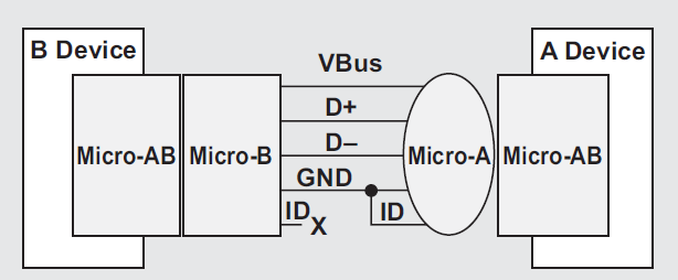
As the name suggests, the Mini/Micro-AB receptacle is designed to accept both the standard Mini/Micro-B plug and the new OTG plug, the Mini/Micro-A. Additionally, two new OTG cables have been introduced: the Mini/Micro-A to B and the Mini/Micro-A to Mini/Micro-B, as illustrated in the image below.
The cable below enables a new OTG device to function as a host when communicating with a traditional USB peripheral.
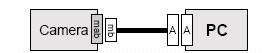
The cable below allows two OTG devices to communicate with each other. For a camera-to-camera connection, both dual-role cameras are equipped with mini-AB receptacles. Therefore, each must function as either a host or a peripheral

The above camera-to-camera connection raises the obvious question of which device acts as the host and which as the peripheral upon connection. The OTG specification resolves this question in a very simple manner: the cable determines the roles.
In below picture, two dual-role devices are connected using a micro-A to micro-B cable. The camera contains a printer driver; however, the micro-A end of the cable is connected to the printer, making it the default host (as the USB ID pin is connected to ground). This setup may appear to be incorrect—the camera must be the host in order to print.

This issue is handled by the USB OTG feature of the Host Negotiation Protocol (HNP). Using HNP, the camera in the above scenario can assume the host role (Roles Exchange), even though the initial cable connection designates the printer as the default host (A-Device).
Schematic for USB OTG Like Connector Implementation
The following circuits illustrate USB OTG implementations. Your MPU/MCU may have dedicated USB ID and USB VBUS Enable pins as a part of USB controller. If these are not available, GPIOs can be used to detect USB ID and USB VBUS.
In this example, two GPIOs are used: GPIO1 for ID status detection and GPIO2 for VBUS output control, as shown in the schematics below.

By default, the USB is configured as a device(ID Pin Pulled-High), and GPIO2 disables the USB VBUS power supply (USB switch), waiting for an external USB host to provide power. When an external USB peripheral is plugged in, the system checks the GPIO1 ID status:
- If GPIO1 = 1, the configuration remains unchanged. Once power is received from the external host on VBUS, the device pulls up the bus line and initiates a handshake with the host.
- If GPIO1 = 0, indicating that the ID pin is connected to ground, GPIO1 generates an interrupt, prompting the CPU to configure the USB as a host. GPIO2 then enables VBUS to supply power to the external USB peripheral. The host pulls down the bus line, waits for the pull-up signal from the external USB peripheral, and then initiates a handshake.
Host Negotiation Protocol (HNP) in USB OTG
The Host Negotiation Protocol (HNP) allows the host function to be transferred between two directly connected OTG devices. HNP enables the peripheral to become the host once the initial host has finished using the bus, facilitating seamless communication and enhancing the end-user experience by eliminating the need to disconnect and reverse the cable.
In the previous example, HNP eliminates the need for the user to switch the cable connections to change control of communications between the devices.
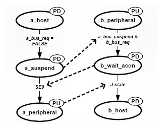
Above figure which contains the states relevant to HNP for A- and B-device behaviors into one simplified diagram.
The A device is on the left, and the B-device is on the right. As in the OTG spec, state names with the “a_” prefix pertain to the A-device, and state names with the “b_” prefix pertain to the B-device. The Figure state names and the italicized signal names are taken directly from the OTG specification. The added “PU” ovals indicate connection of the D+/D– pull-up resistor, and the “PD” ovals represent connection of the 15-kΩ pull-down resistors on D+ and D–.
Here’s a Host Negotiation Protocol (HNP) role-switching process:
- Initial State:
- A-device (Host) → a_host state (Pull-down resistors ON)
- B-device (Peripheral) → b_peripheral state (Pull-up resistor ON)
- A-device A-device performs all the normal host duties, including bus
reset, generating SOF packets, enumerating the B-device, and suspend-resume. In between:
- A-device checks if B-device supports HNP (via OTG descriptor).
- A-device enables HNP on B-device (`Set_Feature(b_hnp_enable)`).
- A-device negates `a_bus_req` signal and suspends the bus (stops traffic for ≥3ms), indicating that it does not need to use the bus.
- B-device attempts to become Host:
- B-device detects bus suspension.
- If B-device is having HNP-enabled and wants to request the bus (`b_bus_req` asserted), it enters “b_wait_acon state”.
- B-device disconnects (turns OFF pull-up, turns ON pull-downs → SE0(single-ended – zero) state).
- A-device switches to Peripheral Mode:
- A-device detects SE0 and transitions to a peripheral state.
- A-device connects as a peripheral by turning ON its D+ pull-up resistor (J-state).
- B-device becomes Host:
- B-device detects J-state (A-device connected as peripheral).
- B-device transitions to “b_host state” → Role reversal is complete.
- Reversing the Role Again (B-Host to A-Host):
- B-device suspends the bus.
- A-device detects suspension and disconnects.
- A-device regains host role.
Here’s a flowchart representation of the Host Negotiation Protocol (HNP) role-switching process:

USB OTG Session Request Protocol
To conserve power, the OTG supplement allows an A-device to keep VBUS turned off when the bus is not in use. If the B-device needs to use the bus while VBUS is turned off, it must request the A-device to supply power on VBUS. For this purpose, the OTG supplement defines the Session Request Protocol (SRP).
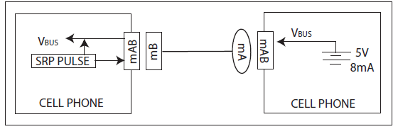
An OTG session is defined as the period during which the A-device supplies VBUS power. Notably, the A-device always provides VBUS power, even when functioning as a peripheral due to the Host Negotiation Protocol (HNP). To conserve power—especially in battery-powered devices such as cell phones—the A-device can end a session by turning off VBUS.
The relationship between SRP and HNP are as follows:
- Dual-role devices must be capable of both initiating and responding to SRP.
- The A-device always supplies VBUS. Even if two dual-role devices use HNP to switch roles—making the B-device the host and the A-device the peripheral—the A-device continues to provide VBUS.
- Non-dual-role devices, which inherently do not support HNP, can still initiate SRP. For example, a battery-powered mouse can request a session from a dual-role device.
Summary of USB On-The-Go (OTG) Overview
- Introduction to USB OTG:
USB On-The-Go (OTG) is an extension of USB 2.0 that allows devices to function as both a host and a device dynamically. This eliminates the need for a dedicated host, enabling direct device-to-device communication, such as a camera printing photos directly to a printer or MP3 players exchanging files. - Key Features of USB OTG:
- Supports dual-role devices (host and peripheral mode).
- Uses Micro-AB receptacles for flexible connectivity.
- Introduces Session Request Protocol (SRP) and Host Negotiation Protocol (HNP).
- Allows dynamic power management for battery-powered devices.
- USB OTG Electrical Characteristics:
Defines voltage, current, and resistance parameters for A-devices and B-devices, ensuring safe and efficient power management. - Differences Between USB OTG and Standard USB:
- Uses specialized cables and connectors (Mini-USB OTG vs. Micro-USB OTG).
- Supports role switching via HNP without unplugging cables.
- Allows power conservation with SRP, enabling the B-device to request power when needed.
- USB OTG Connection & Role Switching (HNP):
- The ID pin determines the default host (A-device).
- HNP allows role switching dynamically between the host and peripheral without disconnecting.
- Session Request Protocol (SRP) for Power Management:
- Allows the B-device to request the A-device to turn on VBUS when needed.
- Conserves power in battery-operated devices like smartphones.
- Relationship Between SRP and HNP:
- Dual-role devices must support both protocols.
- The A-device always supplies VBUS, even when switching roles using HNP.
- Non-dual-role devices (e.g., a battery-powered mouse) can still initiate SRP to request power.
Author Profile
- 20+ years embedded hardware design professional with a burning passion for teaching. Sharing the intricate world of embedded hardware is my mission and joy.
Latest entries
 Tech Updates30 November 2025STM32WBA6: The Next-Generation MCU Powering Secure Short-Range Wireless Designs
 Blogs24 November 2025High-Speed PCB Layout Design Guide-104
 Tech Updates14 September 2025Renesas Launches RL78/L23 Ultra-Low-Power MCUs to Power Smarter Home Appliances
 Blogs7 September 2025High-Speed PCB Layout Design Guide-103


