Ethernet ports are vulnerable to electrostatic discharge (ESD), electrical fast transient (EFT), lightning, and cable discharge events (CDE), which can damage Ethernet PHY chips. To protect against these threats, external transient voltage suppressor (TVS) diodes are often used. While common wisdom suggests placing TVS diodes near the RJ-45 connector and connecting each signal line to the ground, it is more effective to connect the TVS diodes across the signal pairs on the PHY side of the connector. This placement ensures better protection by clamping voltage spikes before they reach the PHY, reduces ground bounce, and maintains signal integrity by leveraging the differential signaling used in Ethernet.
In this blog, we will discuss why TVS diodes should be placed between the PHY and the magnetics, rather than between the magnetics and the RJ-45 connector. We will examine Ethernet protection methodology in detail, exploring the reasons behind optimal TVS diode placement to ensure maximum protection for Ethernet PHY chips.
Ethernet Interfaces
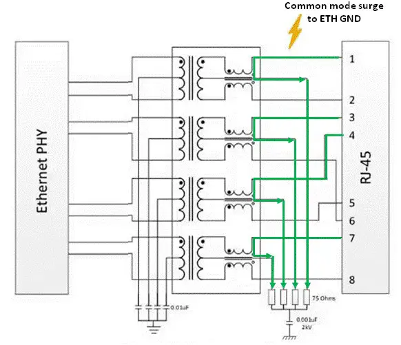
A typical Ethernet port includes isolation transformers, common mode chokes, and port termination, as shown in Figure. The transformers have a minimum isolation rating of 1500 VRMS (2.1kV), as required by the IEEE 802.3 standard for Ethernet interfaces. Common mode chokes, often integrated with the isolation transformers, serve to reduce EMI emissions. Ethernet ports are commonly terminated using the “Bob Smith” technique, which employs a 75 Ohm resistor for a common mode impedance match at each signal pair, collectively connected via a high voltage 1000pF capacitor to chassis ground. This termination aims to further reduce common mode emissions.

Ethernet Interfaces electrical and compliance requirements
- The data signals used in an Ethernet port vary between 1.0V and 2.5V (Typical 2V) with maximum data rates of 1000Mbps
- Lightning Induced Surges (IEC61000-4-5, GR-1089, ITU), for a 25A 8×20μs waveform. Both differential and common mode surge
- ESD or Electrostatic Discharge (IEC61000-4-2)
- EFT or Electrical Fast Transient (IEC61000-4-4)
- CDE or Cable Discharge Event
Objective
- Protect high-speed data and transmission lines
- Very low capacitance protection to support high speed Ethernet link
- Low clamping voltage as per Ethernet standard (2V to 2.5V)
- Flow-through trace routing to support high speed Ethernet link
- High ESD, surge and EFT capability
Common Mode & Differential Mode Surges
Transient events affecting Ethernet ports can be either common mode or differential mode in nature. During a common mode surge, all conductors develop the same instantaneous voltage with respect to ground. Since all conductors (of RJ54 Connector) are at the same potential, current does not flow from one conductor to another but instead flows through the equipment to the ground. A common path for this current is through the conductor to the ground via the transformer center tap and the Bob Smith termination circuit (Figure Below)
A surge that appears between two conductors in the same cable is called a “differential surge.” In this case, different voltage levels appear at the RJ-45 conductors, causing current to flow into the Ethernet port on one line of a differential pair, through the transformer, and out of the port on the other line. The transient current that flows through the transformer primary charges the windings and induces surge current on the secondary, as shown in Figure.
Even if a TVS diode is placed at the RJ-45 Ethernet connector, it can only provide a path for surge current to Earth Ground but cannot prevent the surge current passing through the transformer. This induces a differential mode surge current on the secondary side of the transformer, potentially damaging the PHY.
Ethernet Protection Strategy
Now that we have a better understanding of the types of surges we can expect on an Ethernet port, it is clear that connecting a protection device on the line side of the transformer causes more problems than it solves. For optimal protection, the TVS diodes should be placed as close to the PHY pins as possible, oriented correctly, and chosen for their fast response and appropriate voltage handling capabilities. Moreover, in practice it is not needed. Below are few impotent points that can be considered.
- Transformer isolation and termination networks provide protection against common mode surges & have a minimum isolation voltage of 2.1kV. Many commercially available transformers can withstand transient voltages in the 4-8 kV range.
Protection against differential surges requires the use of TVS diodes. Below Figure illustrates this protection scheme.
Advantages of Placing Protection on the PHY Side
- The magnitude and duration of surge current are attenuated by the transformer windings.
- As surge current increases in the primary winding (Line side), the transformer saturates and stops coupling current to the secondary winding.
- The amount of attenuation varies by vendor and magnetics configuration.
The Ethernet protection strategy involves several components designed to mitigate the effects of both common mode and differential mode surges. Here’s how each element works:
-
Bob Smith Termination
- Purpose: To reduce interference caused by common-mode current flows and susceptibility to interference from unused wire pairs.
- Termination: The center tap of the primary side winding of the Ethernet transformer is used for the “Bob Smith” termination.
- For each wire pair, a 75 Ω resistor is connected to a common point called the “star point.” This helps balance the current and reduce common-mode noise.
- Function: By referencing an impedance of about 145 Ω per wire pair and grounding through capacitors, this termination helps balance the system and reduces noise, enhancing EMC.
-
Common-Mode Chokes
- Purpose: To suppress common-mode noise.
- Function: These chokes present high impedance to common-mode signals (noise) while allowing differential-mode signals (data) to pass with minimal attenuation. This significantly improves EMC by reducing the potential for common-mode surges to affect the system.
-
Transformers
- Purpose: To provide galvanic isolation and protect against differential mode surges.
- Function: Transformers isolate the Ethernet interface from the rest of the system, preventing surges on the line from reaching sensitive components. They work in conjunction with common-mode chokes to enhance overall protection.
-
Capacitors and Resistors
- Purpose: To provide a controlled path for high-frequency noise to be shunted to the ground and to balance the impedance.
- Function: The capacitors (typically with a dielectric strength of at least 2 kV or above) 100 pF but can be up to 2 nF and resistors (75 Ω) help in mitigating high-frequency noise and balancing the impedance, ensuring minimal reflection and interference that can cause signal degradation.
- The chosen capacitor value affects the filter’s cutoff frequency. Higher capacitance provides better low-frequency noise suppression but could affect signal integrity if too high
Cable Discharge Event (CDE)
Cable Discharge Event (CDE) is distinct from electrostatic discharge (ESD) and involves high voltages generated within twisted-pair cables due to environmental factors. The IEEE 802.3 standard specifies isolation voltages of 2250 VDC and 1500 VAC to prevent CDE-related connector failures. Effective CDE protection requires good layout practices, adequate creepage and clearance on PCBs, and careful component selection.
To prevent arcing during these events, these isolation requirements apply to the RJ-45 connector as well as to the isolation transformers. To break down and sparking on the circuit board, the line side printed circuit board and the ground should have sufficient creepage and clearance between traces. Lab tests have shown that to withstand 2000V of transient voltage, the FR4 circuit board trace spacing should have a separation of at least 250 mils. (Source:www.national.com)
CDEs can reach several thousand volts, primarily due to triboelectric (friction) and electromagnetic induction effects, such as pulling cables on carpets or through conduits. Charge accumulation occurs in unterminated cables and can be retained for long periods, particularly in low humidity environments. Upon connection, this charge can discharge through various paths, potentially damaging connectors, transformers, or transceivers.
Designers should focus on diverting energy away from IC devices by placing TVS Diode line side too and ensuring proper grounding. Special precautions are needed for cables longer than 60m, as they can store more charge.
Ethernet Protection Strategy Summary
Overview of Ethernet Port Vulnerabilities
Ethernet ports are susceptible to various electrical threats, including:
- Electrostatic discharge (ESD)
- Electrical fast transients (EFT)
- Lightning strikes
- Cable discharge events (CDE)
Importance of TVS Diode Placement
To protect Ethernet PHY chips from these threats, Transient Voltage Suppressor (TVS) diodes are commonly used. Optimal placement of TVS diodes is crucial:
- Preferred Placement: Between the PHY and the magnetics (transformers and chokes)
Ethernet Interface Components
Typical Ethernet ports include:
- Isolation Transformers: Provide at least 1500 VRMS isolation, often up to 2-8 kV.
- Common Mode Chokes: Reduce EMI emissions.
- Port Termination: Uses the “Bob Smith” technique for common mode impedance matching.
Electrical and Compliance Requirements
Ethernet ports must meet various standards:
- Data Signal Voltage: Between 1.0V and 2.5V, typically 2V
- Data Rates: Up to 1000Mbps
- Surge Protection: Must withstand 25A 8×20μs waveforms
- ESD and EFT Standards: Compliance with IEC61000-4-2 and IEC61000-4-4
Common Mode and Differential Mode Surges
- Common Mode Surges: All conductors have the same voltage relative to ground, causing current to flow through center tap pin of transformer to the ground.
- Differential Mode Surges: Voltage differences between conductors in the same cable cause current to flow through the Ethernet port, potentially damaging the PHY.
Protection Strategy
- Common Mode Protection: Transformers and termination networks provide robust protection.
- Differential Mode Protection: TVS diodes are essential for clamping differential surges, and their placement near the PHY enhances effectiveness.
- Advantages of PHY-Side Placement:
- Surge current is attenuated by transformer windings.
- Transformer saturation prevents current coupling to the secondary winding.
- Finally TVS placed on PHY side helps to protect it against current induced against secondary winding of Transformer.
Key Protective Elements
- Bob Smith Termination: Reduces common-mode interference and Impedance matching.
- Common-Mode Chokes: Suppress common-mode noise while allowing data to pass.
- Transformers: Provide isolation and work with chokes to protect against surges.
- Capacitors and Resistors: Help in noise mitigation and impedance balancing.
Cable Discharge Events (CDE)
CDEs occur due to high voltages generated in cables by friction and electromagnetic induction. Effective CDE protection includes:
- Adhering to IEEE 802.3 isolation standards
- Ensuring proper layout practices with adequate creepage and clearance
- Selecting appropriate components and grounding methods
Author Profile
- 20+ years embedded hardware design professional with a burning passion for teaching. Sharing the intricate world of embedded hardware is my mission and joy.
Latest entries
 Tech Updates30 November 2025STM32WBA6: The Next-Generation MCU Powering Secure Short-Range Wireless Designs
 Blogs24 November 2025High-Speed PCB Layout Design Guide-104
 Tech Updates14 September 2025Renesas Launches RL78/L23 Ultra-Low-Power MCUs to Power Smarter Home Appliances
 Blogs7 September 2025High-Speed PCB Layout Design Guide-103


