In our earlier blog High-Speed PCB Layout Design Guide, we covered several foundational aspects of high-speed PCB design. These included how to determine whether a design qualifies as high-speed based on factors like knee frequency and trace length, as well as important footprint design considerations to minimize parasitic effects.
We also explored effective floor planning and component placement strategies to ensure optimal signal integrity, discussed best practices for component orientation to support efficient routing and manufacturability, and outlined functional PCB component placement guidelines to balance performance, thermal management, and EMI control.
This particular blog will focus on Selecting PCB Materials for high-Speed designs.
Key Base PCB Material Properties for High-Speed layout Design
When choosing a base PCB material for the layout, it’s essential to evaluate specific material properties to ensure they align with your application requirements. For high-speed designs in particular, the following PCB material characteristics play a critical role and must be carefully considered during material selection.
Thermal Properties
- Glass Transition Temperature (Tg):
- The temperature at which the PCB material changes from a rigid to a soft, rubbery state.
- A higher Tg improves thermal stability and resistance to delamination during soldering or reflow.
- Example: –
- 370 HR: 180°C
- Rogers 4350B: 280°C
- Decomposition Temperature (Td):
- The temperature at which the material begins to chemically decompose.
- Higher Td ensures the material maintains structural integrity during high-temperature processing (during soldering and reflow.)
- Example: –
- 370 HR: 340°C
- Rogers 4350B: 390°C
- Thermal Conductivity (k):
- Measures how well the material conducts heat. This describes the ability of a material to transfer heat.
- Higher thermal conductivity helps dissipate heat from power components and improves thermal performance.
- Example: –
- 370 HR:4 W/m·K
- Rogers 4350B: 0.69 W/m·K
- Coefficient of Thermal Expansion (CTE):
- Describes how much the material expands when heated.
- Lower CTE is desirable for multilayer PCBs to prevent misalignment or cracking during thermal cycling. Z-axis CTE is most critical—should be < 70 ppm/°C ideally.
- Example: –
- 370 HR: X: 13 ppm/°C, Y: 14 ppm/°C, Z: 45 ppm/°C
- Rogers 4350B: X: 10 ppm/°C, Y: 12 ppm/°C, Z: 32 ppm/°C
Electrical Properties
- Dielectric Constant (Dk):
- Indicates how much the material can store electrical energy.
- Lower and more stable Dk across frequency and temperature ensures consistent impedance and better signal integrity in high-speed circuits.
- Loss Tangent or Dissipation Factor (Tan δ or Df):
- Represents energy loss as heat in the dielectric when signals pass through.
- Lower Df is critical for minimizing signal attenuation and distortion in high-speed or RF applications.
Question -Is there an universal ‘Best’ PCB material for high speed design?
No single material is ideal for every high-speed PCB design, as different interfaces and protocols have varying bandwidth requirements. As channel bandwidth increases, the need for materials with specific characteristics also rises. These include:
- Low loss tangent (Df)
- Smooth copper surface
- Consistent dielectric constant (Dk) across the bandwidth
Selecting the right PCB material begins with understanding the required channel bandwidth. Designers often refer to application notes, reference designs, or proven development boards, which offer a reliable starting point with validated signal integrity.
To estimate acceptable signal loss in a physical channel, a practical rule of thumb is to use whichever occurs first:
- The lowest frequency at which return loss drops to -10 dB, or
- The lowest frequency at which insertion loss reaches -3 dB for the expected trace length
Though not perfect for every case, this approach gives a reasonable estimate of the usable bandwidth of a transmission line.
High speed PCB Material Category
When selecting high-speed PCB laminates, designers must carefully balance signal loss, manufacturability, and cost. Signal integrity is critical in high-speed designs, so materials with a stable dielectric constant (Dk), low dissipation factor (Df), and smooth copper surface are preferred to minimize insertion loss and maintain impedance consistency.
At high frequencies, even slight variations in Dk or rough copper can significantly degrade signal quality due to skin effect and wavelength-related effects.
Manufacturability is another key factor—some advanced laminates are more difficult to drill, laminate, or process, especially in complex stackups or HDI designs. Compatibility with standard fabrication processes, thermal stability (Tg), and mechanical reliability (CTE matching) must be ensured to avoid issues like delamination or warping.
Lastly, cost considerations cannot be ignored; high-speed materials like Rogers or Megtron are considerably more expensive than FR-4.
Using hybrid stackups or overdesigning with ultra-low-loss materials for low-bandwidth interfaces can lead to unnecessary expenses. Therefore, careful analysis of signal bandwidth, manufacturing capabilities, and budget is essential when choosing the appropriate PCB laminate for high-speed applications.
Some of the following tables provide a comparison of PCB material categories, their corresponding speed ranges, and the preferred materials for each category.
|
Speed / Loss Category |
Description |
Example Material |
|
Normal Speed, Normal Loss |
Most common FR-4 materials; Dk vs frequency not flat; high dielectric loss; suitable for a few GHz digital/analog. |
Isola 370HR |
|
Medium Speed, Medium Loss |
Flatter Dk vs frequency response; ~50% lower dielectric loss than normal speed materials; suitable up to ~10 GHz. |
Nelco N7000-2 HT |
|
High Speed, Low Loss |
Flat Dk vs frequency response and low dielectric loss; lower electrical noise; suitable for high-speed designs. |
Isola I-Speed |
|
Very High Speed, Very Low Loss (RF/Microwave) |
Flattest Dk vs frequency response; least dielectric loss; suitable up to ~20 GHz; ideal for RF/microwave applications. |
Isola Tachyon 100G |
The table below outlines various communication interfaces along with their corresponding recommended PCB material options.
|
Example Interfaces |
Channel Bandwidth |
Material Options |
|
SPI or slower |
30 MHz |
Standard FR-4 |
|
USB, MIPI |
~1 GHz |
Standard FR-4 |
|
HDMI |
2.5 to 24 GHz |
Low-loss FR-4 up to Megtron |
|
<1Gbps Ethernet |
<1 GHz (depending on modulation) |
Standard FR-4 |
|
>1Gbps Ethernet |
Based on Nyquist frequency |
Low-loss FR-4 up to Megtron |
|
PCIe 1–5 |
Up to 2 GHz/lane (Gen 5) |
Low-loss FR-4 |
|
PCIe 6 |
2 GHz/lane (based on PAM4) |
Advanced FR-4 |
The tables below list various manufacturers and their PCB material names, along with the application areas they are best suited for based on specific signal speed categories.
|
Low/Medium Speed (0 to 500MHz) |
||
|
Manufacturer |
Material Name |
Application Areas |
|
Isola |
FR370HR |
Medium Speed, Normal Loss |
|
Nelco |
N7000-2 HT |
Medium Speed, Medium Loss |
|
High Speed (500MHz to 3 GHz) |
||
|
Manufacturer |
Material Name |
Application Areas |
|
Isola |
FR408HR |
High Speed, Low Loss |
|
Isola |
I-Speed |
High Speed, Low Loss |
|
Panasonic |
Megtron6 R-5775 |
High Speed, Low Loss |
|
Very High Speed/Microwave (3 GHz and above) |
||
|
Manufacturer |
Material Name |
Application Areas |
|
Isola |
I-Tera MT40 |
Very High Speed/Frequency, Very Low Loss |
|
Rogers |
RO3003 |
Very High Speed/Frequency, Very Low Loss |
|
Rogers |
RO4350 B |
Very High Speed/Frequency, Very Low Loss |
|
Isola |
Tachyon-100G |
Very High Speed/Frequency, Very Low Loss |
|
Isola |
Astra MT77 |
Very High Speed/Frequency, Very Low Loss |
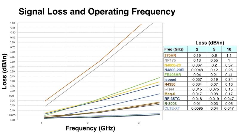
Signal Loss and Operating Frequency
PCB electrical performance is mainly influenced by signal loss at the operating frequency, the potential for weave effect, and the material’s manufacturability when constructing the layer stack-up. A key aspect to evaluate is the relationship between signal loss and frequency. Generally, signal loss increases as operating frequency rises, but some materials have lower loss and perform better at high speeds. These high-performance materials offer better signal integrity but are more expensive due to their advanced properties and processing requirements. This graph highlights which materials are likely to deliver better electrical performance at higher frequencies.
Let’s look at how material cost compares across different classifications. As shown in the chart, materials with lower signal loss generally come at a higher price.
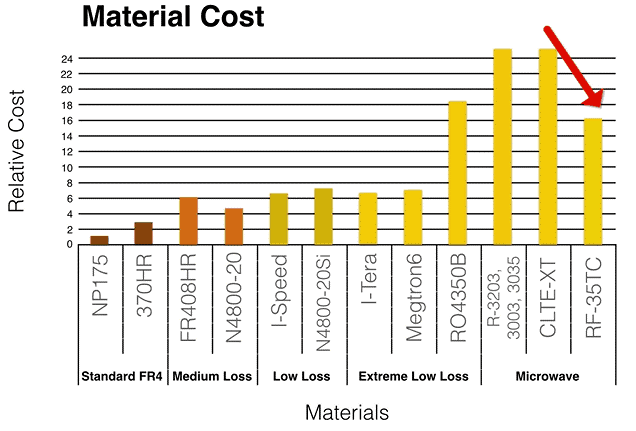
Choosing the right material depends on your project’s specific needs. For example, while Rogers 4350B offers performance similar to Megtron 6 or I-Tera, it tends to be more expensive. In the microwave category, Taconic RF-35 delivers comparable performance to other materials but is roughly 30% more cost-effective.
Summary
High-speed PCB Key Material Properties
- Thermal Properties:
- Tg (Glass Transition Temp): Higher Tg = better thermal durability (e.g., Rogers 4350B: 280°C vs. 370HR: 180°C).
- Td (Decomposition Temp): Higher Td improves heat resistance during soldering.
- Thermal Conductivity: Affects heat dissipation (e.g., Rogers 4350B > 370HR).
- CTE (Thermal Expansion): Lower Z-axis CTE preferred for multilayer boards.
- Electrical Properties:
- Dk (Dielectric Constant): Lower and stable Dk ensures impedance control.
- Df (Loss Tangent): Lower Df minimizes signal loss and distortion.
Material Categories and Examples
Low/Medium Speed (0–500 MHz):
- Isola 370HR, Nelco N7000-2 HT
High Speed (500 MHz–3 GHz):
- Isola FR408HR, I-Speed, Panasonic Megtron6
Very High Speed (>3 GHz):
- Rogers RO3003, RO4350B, Isola Tachyon-100G, I-Tera MT40, Astra MT77
Signal Loss vs Frequency
- Signal loss rises with frequency.
- Lower-loss materials preserve signal integrity at higher speeds but are more expensive due to advanced processing.
Cost Comparison
- Materials with lower signal loss generally cost more.
- Example: Rogers 4350B is more expensive than Megtron 6 or I-Tera despite similar performance.
- Taconic RF-35 offers ~30% cost savings in microwave applications with comparable performance.
Author Profile
- 20+ years embedded hardware design professional with a burning passion for teaching. Sharing the intricate world of embedded hardware is my mission and joy.
Latest entries
 Tech Updates30 November 2025STM32WBA6: The Next-Generation MCU Powering Secure Short-Range Wireless Designs
 Blogs24 November 2025High-Speed PCB Layout Design Guide-104
 Tech Updates14 September 2025Renesas Launches RL78/L23 Ultra-Low-Power MCUs to Power Smarter Home Appliances
 Blogs7 September 2025High-Speed PCB Layout Design Guide-103


