The USB 2.0 architecture follows a star network configuration with a single host that controls all connected devices. Connection between devices and the main computer (host) follows a specific structure called the tiered star topology, which organizes devices in layers that branch out like a star.
USB 2.0 Architecture
The USB 2.0 architecture supports a maximum of seven tiers, with each tier branching out from the host’s root hub, allowing up to 127 devices (including hubs) to be connected. Hubs and the host supply power to connected devices, enabling many to operate without an independent power source.
The USB 2.0 architecture limits each USB cable to 5 meters to maintain signal integrity. Data transfers are entirely host-controlled, with the host initiating and scheduling all communication, ensuring an organized data flow and preventing collisions.
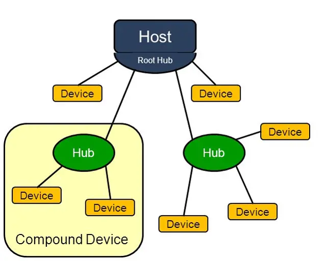
Each device implements one or more functions, like printing or data storage, to provide specific capabilities to the host. This centralized, tiered design enables efficient device management and scalability while maintaining reliable connections across the USB network. Here’s a more detailed look at each component:
1. USB Host
In a USB system, there is only one host, which is the main controller for all connected USB devices. This host uses a “Host Controller” to manage the USB connections.
The Host Controller can be made of hardware, firmware, software, or a mix of these. Inside the host, there is a “root hub” that offers one or more connection points for USB devices to plug in. Roles of USB Host in USB Architecture are as below.
- It controls all access to the USB, granting devices access to the bus as needed.
- The host monitors and manages the USB’s topology and structure.
- It initiates communication with each device once the device identifies itself on the bus.
- If the host doesn’t recognize a device, it can reset the device or disable the port to conserve power.
2. Root Hub
The root hub is an embedded hub inside the host, providing one or more attachment points (ports) for devices. It functions similarly to an external hub, offering standard hub features and serves as the starting point for all USB connections. Roles of Root Hub in USB Architecture are as below.
- From the root hub, additional hubs and devices can be connected, expanding outward into a structured hierarchy.
- The root hub is responsible for managing device connections and disconnections, device reset, and port power. It also handles initial communication with devices when they connect to the bus.
- The root hub is essential for creating the tiered structure and maintaining a centralized point of control over all USB devices connected to the host.
- Since the root hub is part of the host, it does not count toward the limit of five levels of external hubs between the host and any connected device.
3. Hubs
External hubs act as additional connection points between the host and devices, supplying power and relaying data. Each hub can connect several devices directly, expanding the number of USB devices the host can manage. Roles of Hub in USB Architecture are as below.
- Hubs also play an important role in managing data flow. They determine which data is directed to which device, helping avoid data congestion and ensuring that each device receives the necessary data.
- When a hub is connected to the host, it acts as a branching point in the network, allowing additional devices to connect in a star-like pattern around it.
- Hubs are classified as USB devices and must specify in their configuration whether they are bus-powered (drawing power from the USB bus) or self-powered (drawing power from an external source).
- A bus-powered hub draws some power from the host, which may lead to a slight voltage drop (to around 4.7V). Although a bus-powered hub can theoretically draw up to 100 mA and supply up to 400 mA to connected devices, it is generally recommended to use a self-powered hub to ensure stable power and reliable bus signaling.
4. USB Device Definition
A device is any logical or physical entity that performs one or more functions. Examples include keyboards, printers, and storage drives.
- Composite Device:
A composite device has a single address but provides multiple interfaces, each delivering a separate function. For instance, a multifunction printer might combine printing, scanning, faxing, and copying functions within a single device, with each function accessed through a different interface.
- Compound Device:
A compound device consists of a hub with one or more permanently attached devices. The host views each part of a compound device as a separate physical entity. For example, a USB hub with built-in storage would be treated by the host as both a hub and a storage device.
5. Data Flow and Power Management
-
- In this structure, the host controls data flow, determining which device receives data and when. This coordination prevents data conflicts and ensures efficient communication.
- Hubs also distribute power to connected devices, though power may be limited depending on the hub. Some hubs have their own external power source, known as powered hubs, which allows them to provide more power to each connected device.
USB HUB Tiered Structure
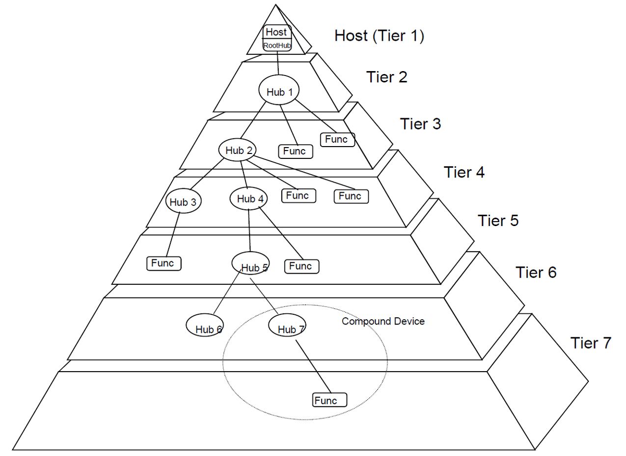
The USB system connects devices to a USB host using a “tiered star” structure. At the center of each star is a hub, which connects to other hubs or devices in a point-to-point manner. This setup creates a series of layers, or “tiers,” with the host at the root tier and hubs or devices branching out from there.
For efficient data transfer, there can only be up to seven tiers in total, including the host tier. This means a maximum of five hubs (not counting the host) can be in the data path between the host and any connected device.
Additionally, “compound devices” (which combine both hub and function capabilities) take up two tiers, so they can’t connect at the seventh tier. Only regular devices can connect at the 7th tier.
Tiered Structure Benefits
-
- The tiered structure of USB ensures that devices are organized in a hierarchy, where each tier represents a level of devices branching from a hub.
- At each level, devices connect to hubs, which then link back up to the root hub and ultimately to the host.
- This hierarchy prevents circular connections, where a device could end up connected back to itself or another device in an endless loop, which could cause data conflicts or network failures.
- Each level in the hierarchy is distinct, and USB enforces specific limits to maintain stability. For example, the standard restricts the number of tiers to avoid overly complex setups and ensure reliable communication across devices.
USB HUB Explained
Hubs play an essential role in the USB plug-and-play setup, making it easy for users to connect devices and offering reliable connections at a low cost and complexity. Hubs act like connection centers, providing multiple connection points (called ports) from a single USB port.
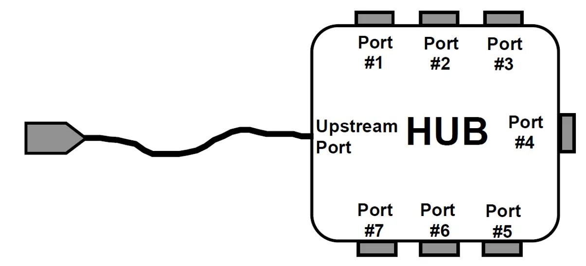
Each hub has an “upstream” port that connects toward the host, and several “downstream” ports for connecting other devices or hubs. Hubs can detect when devices are plugged in or unplugged and can provide power to connected devices. Each downstream port can handle high-, full-, or low-speed devices.
Key Functions of USB Hubs
- Wiring Concentrators: Hubs act as “wiring concentrators,” creating multiple connection points from a single USB port. Each of these connection points, or ports, allows additional USB devices or even more hubs to be connected. Hubs extend the connectivity of a single USB port to support multiple devices, so users don’t need individual USB ports for each device.
- Ports: Hubs create ports, which serve as attachment points for devices. A hub’s upstream port connects toward the host (computer or main controller). Downstream ports are the additional ports on the hub, allowing other devices or hubs to connect. This arrangement lets users connect more devices by “chaining” hubs, creating a branching structure of USB connections.
- Attachment and Power Control: Hubs can detect when a device is attached to or removed from any of its downstream ports, enabling the host to be immediately aware of changes in the connection. Each downstream port on the hub can provide power to connected devices, so devices that draw power from the USB port, like small gadgets, can be powered without needing separate adapters. Each port can be individually enabled and configured to support devices operating at high, full, or low speeds.
USB 2.0 Hub Components
A USB 2.0 hub has three key sections, each with specific roles in managing connections, communication, and data handling:
- Hub Controller: The Hub Controller is responsible for managing communication between the hub and the host. It allows the host to control the hub’s ports, monitor their status, and perform functions like turning ports on and off. Through specific commands, the host can configure how each port on the hub operates and monitor its status (such as whether a device is attached or removed).
- Hub Repeater: The Hub Repeater is a switch that manages the flow of data between the upstream and downstream ports. It allows data from the host to reach each connected device and vice versa. The Hub Repeater includes hardware support for protocol control, such as handling reset and suspend/resume This enables the hub to reset a device if needed, or put it in a low-power mode when inactive and resume it when needed.
- Transaction Translator: The Transaction Translator enables devices connected to the hub’s downstream ports to operate at their native speeds. It allows full-speed (12 Mbps) and low-speed (1.5 Mbps) devices to connect to the hub without slowing down the entire hub connection, as it translates their data to be sent at the hub’s high speed (480 Mbps). This means the hub can serve high-speed data transmission for newer devices while supporting older devices with lower speeds.
Host Communication and Configuration Management
The host (main controller) can communicate with the hub to set up and manage its ports. The hub sends status updates to the host, allowing it to monitor which devices are connected or disconnected. The host can configure each port’s operation, disable or enable specific ports, and provide power and data management tailored to each connected device’s requirements.
1. Speed Support in Hubs
- Full-speed hubs support both low-speed (1.5 Mbps) and full-speed (12 Mbps) devices.
- High-speed hubs support low-speed, full-speed, and high-speed (480 Mbps) devices.
- When a high-speed host connects to a high-speed hub with lower-speed devices (low or full-speed) attached, the hub manages communication using a technique called split transactions, which allows the host to communicate efficiently with lower-speed devices without slowing down high-speed data
2. Isolation of Speed Environments
- High-speed hubs are designed to manage two separate data environments: high-speed (480 Mb/s) and full-/low-speed (up to 12 Mb/s for full-speed, and 1.5 Mb/s for low-speed).
- By isolating these environments, hubs ensure that the high-speed data traffic isn’t slowed down by the slower devices. This isolation allows high-speed devices to communicate efficiently without interference from full-/low-speed devices.
3. Support for Older USB Devices
- The USB standard allows older USB 1.1 devices (which operate at full or low speeds) to connect to newer high-speed hubs. This backward compatibility is crucial in mixed-device setups, where a range of devices with varying data speeds need to operate together.
- When a full-/low-speed device is attached to a high-speed hub, the hub manages this connection so that it doesn’t interfere with the high-speed devices. This allows the USB ecosystem to support both old and new devices without requiring entirely separate connections.
4. Bandwidth Expansion
- Each high-speed hub can essentially add more bandwidth specifically for full-/low-speed devices by supporting additional full-/low-speed buses. Think of these as extra “lanes” for slower devices, allowing more of them to operate without affecting the host’s performance.
- Each hub can support multiple full-/low-speed connections up to 12 Mb/s per bus, depending on the number of ports available. This design allows for more full-/low-speed devices to be connected without the need to add additional host controllers, effectively expanding the system’s capacity.
5. Device Limit Management
- Even though multiple full-/low-speed buses can be created by adding hubs, a single host controller can still only manage up to 127 devices. This limit applies regardless of the speed of the devices or how many hubs are connected.
- This constraint ensures that even a complex network of devices remains manageable by the USB system, avoiding overloading the host controller.
6. Hub Involvement in Device Enumeration
-
- During the enumeration process, the host interacts with hubs to assign addresses to devices.
- The host communicates with the hub to specify the port where the device is connected, initiating the enumeration process for that device.
- Once a device is assigned an address, all further communications reference this unique address, enabling the host to recognize and communicate with each device individually.
- After completing enumeration for one device, the host moves to other hub ports to enumerate any additional devices that may be connected.
Summary
The USB 2.0 architecture connects a single host to multiple devices in a structured network called a “tiered star” topology. It allows up to seven layers (or tiers) from the host to the furthest connected device, supporting up to 127 devices (including hubs). This system limits each USB cable to 5 meters, ensuring stable connections. Hubs play a critical role, acting as connection points that branch out from the host’s root hub to form a structured hierarchy of connected devices. Hubs manage data flow, power distribution, and detect when devices are connected or disconnected.
Key Components of USB 2.0 Architecture
- USB Host: The host is the main controller, managing all USB data flow and power supply. Through the Host Controller, it communicates with each connected device, controlling access to the USB network, initiating data transfers, and managing device configurations.
- Root Hub: Integrated within the host, the root hub is the starting point for all connections, enabling USB devices to plug in and branch out from the host. It handles port power and connection management and does not count toward the limit of external hubs in the network.
- External Hubs: These provide additional ports and can connect to multiple devices, acting as branches in the USB tree. Hubs are either bus-powered or self-powered, with self-powered hubs generally providing more stable power. Hubs manage data direction, ensure proper power distribution, and enable multi-speed device connectivity (high, full, and low speeds).
- USB Devices: Any peripheral device (such as keyboards, printers, or storage) that performs a specific function. USB devices can be simple (single-function), composite (multiple functions like a multifunction printer), or compound (a hub with attached devices).
- Data Flow and Power Management: The host controls all data transfers, scheduling communication between devices to prevent conflicts. Hubs manage power distribution, with high-speed hubs capable of supporting both high- and low-speed devices without causing delays.
- Speed and Compatibility: USB 2.0 hubs are backward compatible, allowing older USB 1.1 devices to connect at full- or low-speed without affecting high-speed traffic. This ensures that all devices, regardless of generation, can connect and operate together.
- Device Limit and Enumeration: The USB system can manage up to 127 devices, including hubs. During the enumeration process, the host assigns unique addresses to each connected device, enabling it to recognize and manage each one independently.
This tiered and controlled USB architecture enables reliable data flow, power management, and seamless support for diverse devices and speeds, ensuring compatibility and scalability across the USB ecosystem.
Author Profile
- 20+ years embedded hardware design professional with a burning passion for teaching. Sharing the intricate world of embedded hardware is my mission and joy.
Latest entries
 Tech Updates30 November 2025STM32WBA6: The Next-Generation MCU Powering Secure Short-Range Wireless Designs
 Blogs24 November 2025High-Speed PCB Layout Design Guide-104
 Tech Updates14 September 2025Renesas Launches RL78/L23 Ultra-Low-Power MCUs to Power Smarter Home Appliances
 Blogs7 September 2025High-Speed PCB Layout Design Guide-103

