USB 2.0 hardware design requires careful consideration of signal integrity, power management, and PCB layout to ensure reliable high-speed data transfer. Key aspects include proper differential pair routing, controlled impedance, and minimizing EMI.
Designers must follow USB hardware guidelines for connector placement, shielding, and power delivery to maintain compliance and optimize performance. A well-designed USB 2.0 interface enhances device compatibility, reduces noise, and ensures stable communication in embedded systems, consumer electronics, and industrial applications.
Read below topics before getting into USB 2.0 Hardware Design Guidelines-
USB 2.0 Architecture Explained
USB 2.0 Operating Modes
USB 2.0 supports multiple operating modes based on the device’s role and speed capabilities:
-
USB 2.0 Host Mode
In host mode, the MPU/MCU acts as the bus master, responsible for enumerating connected USB devices by detecting them, retrieving their configuration details, and assigning them unique addresses on the USB bus.
It also manages data flow by sequentially polling devices, ensuring that no device transmits without a request from the host. Additionally, the USB host must supply power through the +5V VBUS line, providing the necessary power for connected peripherals. This structured control mechanism ensures efficient and reliable USB communication.
When designing hardware for USB Host, remember the following:
- The USB controller functions as a host, managing data communication.
- It supplies power to connected USB devices.
- Hosts can communicate with multiple devices via a USB hub.
- Use a ferrite bead for VBUS. Place near receptacle.
- Use a switch that can shut off VBUS if current exceeds 500 mA.
- Provide at least 96 uF decoupling capacitance on VBUS. Place near USB receptacle.
- Terminate D+ and D- with 15 ohm serial resistors. Place near MPU/MCU.
- Use an ESD protection device. Place near USB receptacle.
- Select a USB Series A type receptacle
-
USB 2.0 Device Mode
USB devices are bus slaves that provide functionality to the USB host. They must supply configuration information to the host, allowing it to establish and manage the connection. Devices are categorized into different classes based on their functionality, which fall into two main types: hubs and functions.
Hubs expand the number of available attachment points for a host, while functions provide additional capabilities, such as human interface devices (HID), mass storage devices, and communication devices.
USB2.0 Bus-Powered Devices vs USB2.0 Self-Powered Devices
USB devices transmit data or control information over the bus only when requested by the host. Since a USB host supplies +5V via the VBUS line, a USB device can either be bus-powered, drawing power from the USB cable, or self-powered, using an independent power source.
USB 2.0 Bus-Powered Device
A bus-powered device draws power directly from the USB VBUS line (+5V) provided by the USB host or hub. These devices do not require an external power source and rely entirely on the USB connection for power and device takes all of its power from the host computer’s USB interface BUS.
Key Characteristics of USB 2.0 Bus-Powered Device
- Powered solely by the USB host (e.g., PC, laptop, or charger).
- Ideal for low-power peripherals like USB flash drives, keyboards, and mice.
- Limited to drawing up to 500mA (USB 2.0) or 900mA (USB 3.0) unless special power negotiation occurs.
- Must not draw power when the host is turned off or in suspend mode.
- Example Devices: USB Flash Drives, Keyboards & Mice, Webcams (low-power models)
Bus-powered Circuit

- Initial Power-Up: Before enumeration, a USB peripheral must draw no more than 100mA. Devices that operate within this limit under all conditions are classified as low-power devices.
- Post-Enumeration: After the device has been enumerated and power negotiation is complete, it may draw up to 500mA. Devices consuming between 100mA and 500mA are considered high-power devices.
- USB Suspend Mode:
- If the peripheral supports remote wake functionality, it may consume up to 5mA during suspend mode.
- If remote wake is not supported, the peripheral must limit its current draw to 500μA in suspend mode.
- To meet USB-IF electrical certification requirements, peripherals with remote wake capability must include a method for triggering system wake-up via an external event or signal.
USB 2.0 Self-Powered Devices
A self-powered device has its own external power source, such as a battery or power adapter, and does not rely on USB power. These devices may still connect to USB for data transfer, but they device takes all of its power from an external power supply

Key Characteristics of USB 2.0 Self-Powered Device
- Uses an external power supply (e.g., AC adapter, battery).
- Suitable for high-power peripherals like printers, scanners, and external hard drives.
- Reduces power burden on the host, allowing for more stable operation.
- Can function independently of the host in some cases.
- Example Devices: External Hard Drives with AC Adapters, Monitors with USB Connectivity
Additional USB Pins in a USB Controller
- In addition to the standard USB 2.0 pins (VBUS, D+, D-, GND), a USB controller may include additional pins to support host, device, and OTG (On-The-Go) functionality. Below is a detailed description of these pins:

Maximum Theoretical Bandwidth of a USB2.0 Device
Many USB 2 users find that their data transfer speeds between a computer and a USB device are limited to around 30MB/sec, despite the USB 2 specification stating a maximum speed of 480Mb/sec (or 60MB/sec).
In practice, High-Speed (480 Mb/s) USB 2.0 operates with 1-millisecond frames, each divided into 8 microframes. Bulk packets can be up to 512 bytes in size, and the absolute theoretical limit is about 12 to 13 packets per microframe.
Therefore, the theoretical maximum speed of a USB 2 device is:
1000 * 8(Frames) * 512(Byte) * 13(Packets) = 53248000 ~= 53 MB/s
USB2.0 Concept of Grounding
USB connections include power, ground, and two data lines, along with a shield connection provided by the USB cable. Based on my experience with designs utilizing standard USB A-B or A-miniB cables, such as the USB-COM232-Plus1, it is advisable to avoid directly connecting the USB shield to the signal ground on the PCB.
Instead, it is recommended to include pads for a zero-ohm resistor to provide a DC path or a capacitor to create a high-frequency path between the shield and signal ground. An example of an RC combination is provided below, and these values can be optimized based on testing.
This design approach offers flexibility in component selection to minimize signal noise while ensuring EMC compliance.

USB2.0 Inrush Current
For bus-powered peripherals, the USB 2.0 specification mandates that VBUS inrush current must be limited to a level equivalent to a 10μF capacitor in parallel with a 44Ω load under the following conditions:
- During the initial connection (plug-in)
- When a high-power circuit undergoes enumeration and power negotiation
- When resuming from a sleep or suspend state
If larger bulk capacitance is required, it may be used provided that power is applied using a soft-start method to ensure the inrush current limit is not exceeded.
Ferrite Bead Uses on USB2.0 D+/D- lines
The USB specification strictly prohibits the use of ferrite beads on the DP and DM data lines. However, their use is recommended on the VBUS power signal. It is common practice to include bulk and decoupling capacitors, as illustrated in the figure.
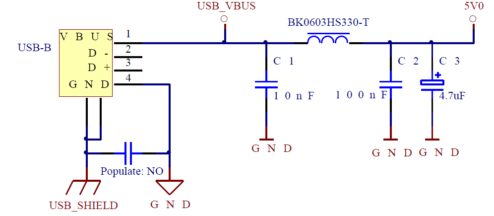
The 10nF capacitor and ferrite bead should be positioned as close to the USB connector as possible for optimal performance. For self-powered peripherals, filtering is generally not required.
Summary of USB 2.0 Design Considerations
- Additional USB Controller Pins
- USB_VBUSEN (VBUS Enable): Controls VBUS power in host applications; connects to an external VBUS switch for power management.
- USB_ID (OTG Role Selection): Determines OTG mode — grounded for Host mode, floating for Device mode.
- USB_VREGI (Voltage Regulator Input): Supplies input power for the internal USB voltage regulator.
- USB_OC (Overcurrent Protection): Monitors device current draw; disconnects power in case of overcurrent events.
- USB 2.0 Operating Modes
- Host Mode:
- Acts as the bus master, managing device enumeration and data flow.
- Supplies +5V power via VBUS and communicates with multiple devices via hubs.
- Key design points: Use a ferrite bead on VBUS, provide at least 96μF decoupling capacitance, and include overcurrent protection.
- Device Mode:
- Acts as a bus slave, responding only to host requests.
- Devices are classified as hubs or functions (e.g., HID, mass storage).
- Power Types in USB Devices
- Bus-Powered Devices:
- Draw power from the USB host, limited to 500mA after enumeration.
- Before enumeration, they must limit current to 100mA.
- In suspend mode:
- Devices with remote wake support can draw up to 2.5mA.
- Devices without remote wake support must limit current to 500μA.
- Self-Powered Devices:
- Operate using an external power source (e.g., battery or AC adapter).
- Suitable for high-power devices like printers and monitors.
- USB 2.0 Maximum Bandwidth
- Theoretical maximum data rate: 53 MB/s
- Achieved by transmitting 13 bulk packets per microframe with 512-byte packets across 8 microframes per millisecond.
- Grounding in USB 2.0
- Avoid direct connection between USB shield and signal ground.
- Use pads for a zero-ohm resistor (DC path) or a capacitor (high-frequency path) to optimize EMC compliance.
- USB 2.0 Inrush Current
- USB VBUS inrush current must be limited to levels equivalent to:
- 10μF capacitor in parallel with a 44Ω load.
- This limit applies during:
- Initial plug-in
- High-power device enumeration
- Resuming from suspend mode
- Larger bulk capacitance may be used with a soft-start method to manage inrush current.
- Ferrite Bead Usage
- Prohibited on DP and DM data lines.
- Recommended on the VBUS power signal, placed near the USB connector.
- For self-powered peripherals, additional filtering is generally unnecessary.
Author Profile
- 20+ years embedded hardware design professional with a burning passion for teaching. Sharing the intricate world of embedded hardware is my mission and joy.
Latest entries
 Tech Updates30 November 2025STM32WBA6: The Next-Generation MCU Powering Secure Short-Range Wireless Designs
 Blogs24 November 2025High-Speed PCB Layout Design Guide-104
 Tech Updates14 September 2025Renesas Launches RL78/L23 Ultra-Low-Power MCUs to Power Smarter Home Appliances
 Blogs7 September 2025High-Speed PCB Layout Design Guide-103


