USB bus enumeration is the process of detecting, identifying, and managing devices attached to the USB bus. When a device is connected, the USB host controller detects its presence, assigns it a unique address, and retrieves its descriptors (e.g., device, configuration) to identify its capabilities and match it with the appropriate driver.
USB enumeration process also includes monitoring for device removals, updating the bus topology, releasing addresses, and notifying software to clean up resources. The dynamic and ongoing nature of USB enumeration ensures seamless plug-and-play functionality, allowing USB devices to be added or removed without requiring a system reboot.
Also Read: USB 2.0 Standard Explained
How USB Enumeration Process Works
When a USB device is attached to or removed from the USB, the host uses below Enumeration Sequence known as bus enumeration to identify and manage the device state changes necessary.
Also Read: USB 2.0 Architecture Explained
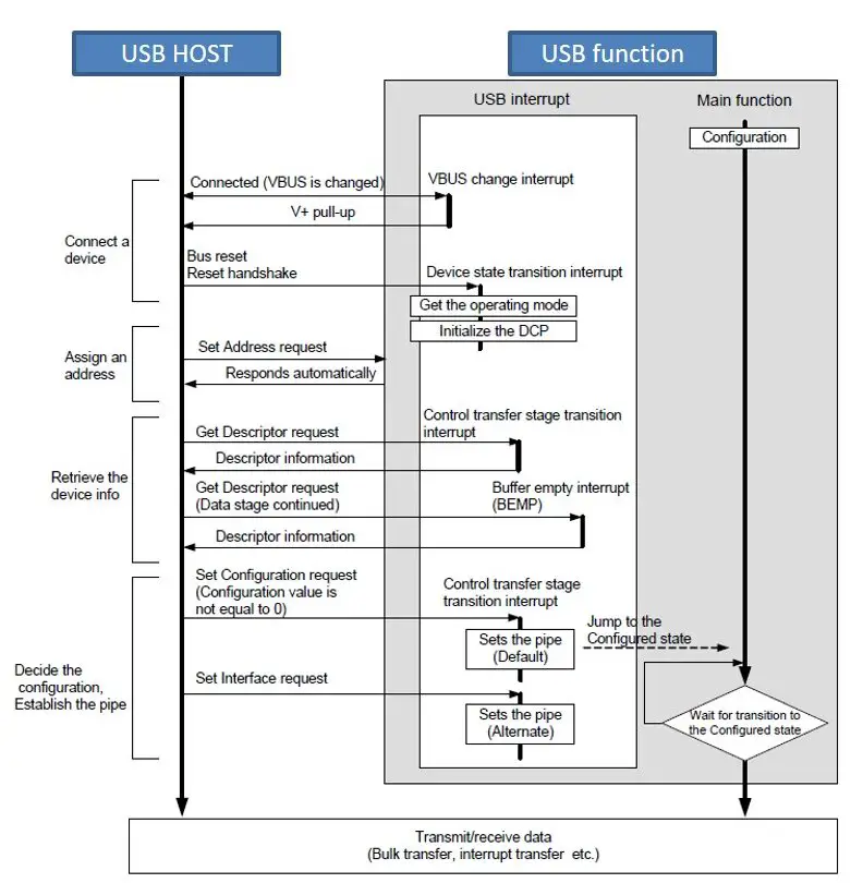
Below are the steps involved in USB enumeration:
Device Attached/Removed
The USB host detects the physical connection of a device. This notify the host that a USB device has been physically connected and initiate the enumeration process.
- Detect the connection or disconnection of a USB device.
- When a new device is physically connected to the USB bus, the host detects its presence through changes in the electrical signaling on the data lines.
- The host starts the enumeration process by assigning a temporary address (typically address 0) to communicate with the device initially.
- At this point, the USB device is in the Powered state and the port to which it is attached is disabled.
USB Device Speed Identification (low-speed, full-speed, or high-speed)
In a USB system, devices identify their speed (low-speed, full-speed, or high-speed) using pull-up resistors on the D+ and D- data lines, which allows the host to recognize the type of device that are connected and adjust communication accordingly.
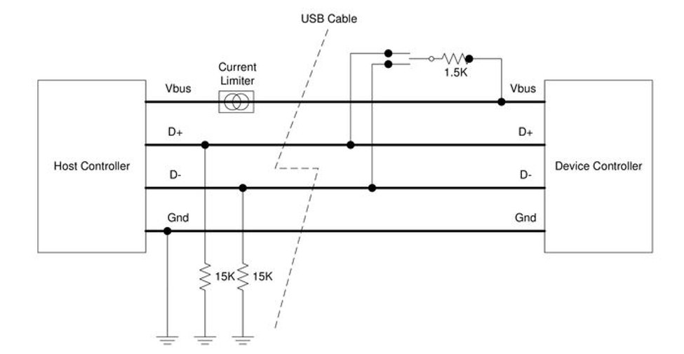
Speed Identification and High-Speed Negotiation
-
- USB devices indicate their speed by pulling either the D+ or D- line high:
- D+ pulled high: Device is full- or high-speed.
- D- pulled high: Device is low-speed.
- High-speed negotiation happens during the bus reset phase. After the reset signal, a high-speed device signals the host with a 480 Mbps chirp.
- High-speed devices start by connecting at full speed (1.5k pull-up resistor to 3.3V). If the hub supports high speed, the device then emits a high-speed chirp during reset to initiate a high-speed connection.
- Once high-speed mode is established, the pull-up resistor is removed to balance the line. High-speed devices do not support low-speed mode; they connect at full speed first, then switch to high-speed upon successful negotiation.
- A USB 2.0 compliant downstream-facing device (hub or host) must support all three speeds: low, full, and high.
- USB devices indicate their speed by pulling either the D+ or D- line high:
Hub Notifies Host
- Now that the host knows the port to which the new device has been attached, the host then waits for at least 100 ms to allow completion of an insertion process and for power at the device to become stable.
- The host enables power through the VBUS line to the connected USB device. The device uses this power to activate its internal circuits and prepare for communication.
- The host then issues a port enable and reset command to that port.
Host Reset Device
The host initiates a reset to ensure the device starts in a known state. To do this host issues a reset signal by holding both data lines low for at least 10 milliseconds. This place the device in its default state, ensuring it is ready to start the enumeration process.
- The host performs the required reset processing for that port.
- Purpose is to initialize the device and synchronize the communication process.
- When the reset signal is released, the port has been enabled. The USB device is now in the Default state and can draw no more than 100 mA from VBUS. All of its registers and state have been reset and it answers to the default address.
Assign Unique Address
The device initially communicates with the host using the default address (0) to establish basic communication before a unique address is assigned. At this stage, the host can only send and receive limited control commands
- The host then assigns a unique address to the device from a pool of available addresses, allowing it to distinguish this device from others on the bus. Each device must have a unique address (between 1 and 127) for the host to communicate effectively within the USB network.
- The host reads the device descriptor to determine, what actual maximum data payload size this USB device’s default pipe can use.
Device Descriptor Request: – Read Configuration Information
The host sends a control transfer to the device requesting its device descriptor. This descriptor contains critical information, such as USB specification version, Vendor ID (VID) and Product ID (PID), Manufacturer and product strings. Purpose of this step is to identify the type of device and its capabilities. This step ensures the host understands the basic properties of the connected device.
- The host reads the configuration information (.INF) from the device by reading each configuration zero to n-1, where n is the number of configurations.
- .INF – A text file that contains all the information necessary to install a device, such as driver names and locations, Windows registry information, and driver version information.
- .SYS – The driver needed to communicate effectively with the USB device
- This process may take several milliseconds to complete.
- Querying Device Capabilities:
- The host sends a series of control requests, called Standard Requests, to the device. These requests include questions about the device’s specifications and capabilities.
- For example, the host may ask for details about the device’s power requirements, such as how much current it needs. This helps the host determine if it can supply enough power for the device to operate.
- The host also inquires about the operational settings the device requires, such as supported data rates, communication modes, and whether the device has specific features that need to be enabled.
Requirements for Device Recognition by the Host
For a device to be recognized and used by the host, three conditions must be met:
-
- Power Availability: The host must be able to meet the power requirements of the device if it relies on USB power (bus-powered).
- Driver Compatibility: The host needs to have the appropriate driver that matches the device’s configuration, allowing it to interpret and communicate with the device properly.
- Bandwidth Availability: The host must have enough available bandwidth on the USB bus to meet the device’s data transfer requirements.
USB Cable and Signal Lines
-
- The USB cable contains four shielded wires:
- Two power wires: +5V and GND.
- Two twisted-pair data lines: for differential data signals.
- The USB cable contains four shielded wires:
Host Controller and Traffic Management
-
- The host controller manages all bus traffic after detecting a device by monitoring the signal lines with pull-up resistors set appropriately for the device’s speed.
- USB supports plug-and-play functionality. When a user plugs in a device, the host detects it, identifies the device, and loads the appropriate driver if available.
- USB is user-friendly, requiring no concern over IRQs, port addresses, or rebooting. Users can simply unplug devices, and the host will unload the driver automatically.
- Exception: For mass storage devices, abrupt disconnections can risk file system corruption if the device isn’t ejected properly.
Configuration Descriptor Request
The host requests the configuration descriptor, which provides detailed information about the device, such as Interfaces (e.g., keyboard, mouse, storage), Endpoints (data streams for communication) & Power requirements. Purpose of this step is to understand how the device operates and what resources it needs.
Retrieving Configuration and Interface Details
- The host requests a set of configuration descriptors from the device. These descriptors contain essential information about the device’s setup and capabilities.
- Configuration descriptors include details on power consumption, number of interfaces, endpoint characteristics, and supported features.
- Each device interface represents a specific function or task it performs (e.g., printing for a printer, capturing images for a webcam). Some devices may have multiple interfaces if they support multiple functions.
- The host gathers and organizes this information to understand how the device should operate and how it fits within the USB system.
Authorization Checks
- Before enabling a device, the host checks:
- If it can supply the required power.
- If it has the appropriate driver matching the device’s configuration.
- If it has sufficient bandwidth to meet the device’s requirements.
- If any of these conditions are not met, the host will not enable the device on the bus.
Endpoint Requirements
- Each device must use Endpoint 0 (bidirectional, supporting both IN and OUT communication) to interact with the host. Endpoint 0 is used for initial setup and control commands.
- Beyond Endpoint 0, a device can have up to 15 additional IN endpoints (for data received by the host) and 15 additional OUT endpoints (for data sent from the host).
Interfaces and Functions
- Endpoints are grouped into interfaces, which are data structures used to implement the device’s functions. Each interface corresponds to a specific function or capability of the device.
- Interfaces are chosen by the host based on the device’s configuration. A configuration defines which interfaces will be active and how they are to be used, allowing for flexible setups depending on the host’s requirements.
Assign Configuration and Initialization
The host sends a “Set Configuration” command to configure the device for operation based on the selected configuration. Porous of this step is to prepare the device for normal operation by enabling specific interfaces and endpoints.
- Based on the configuration and interface information obtained, the host determines if it has a suitable driver to support the device and determine how the USB device will be used. Based on that host assigns a configuration value to the device.
- The driver is a piece of software that enables the host operating system to communicate with the device, interpreting and sending the appropriate data to perform the device’s functions.
- If a matching driver is found, the host loads and initializes it, allowing the device to be used. If a driver is not available, the device may not function properly, or it may operate with limited functionality.
- This driver-matching step ensures that each device’s unique functions can be fully utilized and that the device’s data is interpreted correctly by the host system.
- The device is now in the Configured state and all of the endpoints in this configuration have taken on their described characteristics.
- The USB device may now draw the amount of VBUS power described in its descriptor for the selected configuration. From the device’s point of view, it is now ready for use.
Device Limits
- A USB bus can support a maximum of 127 devices due to the 7-bit address field in each packet (address 0 is reserved).
- Bandwidth or other resources usually limit the number of devices before the maximum is reached.
- Additional ports or hosts can be added if more devices are needed.
Cable and Hub Limits
- The USB bus can have up to 5 hubs with 6 cables, each up to 5 meters in length, between the host and device.
- This setup allows devices to be located up to 30 meters from the host.
Data Transmission
- When the host transmits data, it is sent to all devices connected to enable ports.
- Data travels downwards through each hub, which resynchronizes the data as it relays it.
- Only the addressed device accepts the data; other devices ignore it.
- Only one device can transmit to the host at a time, and only in response to a host request.
- Hubs repeat data received from downstream devices only in the upward direction.
USB Enumeration Process – Summary
USB enumeration is the process by which a host system detects, identifies, and configures USB devices when they are connected or removed. This process ensures seamless plug-and-play functionality. The following key steps summarize the USB enumeration process:
1. Device Detection
- Attach/Remove Detection: The host identifies a device’s physical connection via changes in electrical signaling on the USB data lines.
- The device enters the “Powered” state, and the host begins the enumeration process.
2. Device Speed Identification
- Devices indicate their speed (low, full, or high) through pull-up resistors on D+ or D- lines.
- High-speed devices undergo a negotiation process during the bus reset phase.
3. Power Stabilization and Port Reset
- The host waits for the device power to stabilize (100 ms) and provides power through the VBUS line.
- A reset signal is issued by the host to initialize the device into a default state.
4. Address Assignment
- The host communicates with the device using a temporary address (default: 0) and assigns a unique address (1–127) for identification.
5. Device Descriptor Request
- The host retrieves the device descriptor containing vital information like the USB version, Vendor ID (VID), Product ID (PID), and supported features.
6. Configuration Descriptor Request
- The host requests configuration descriptors to understand the device’s interfaces, endpoints, power requirements, and capabilities.
- Endpoint 0 is used for control commands, while additional endpoints are configured as per the device’s specifications.
7. Driver Matching and Initialization
- The host determines if an appropriate driver is available to support the device.
- If a matching driver is found, it is loaded, and the device is configured for operation.
8. Device Initialization and Operation
- The device enters the “Configured” state, with endpoints and interfaces enabled as described in its configuration.
- The device is now ready for normal use and can draw the power specified in its descriptor.
Additional Details:
- Bus Limits: A single USB bus can support up to 127 devices.
- Power, Driver, and Bandwidth Checks: Devices are only enabled if sufficient power, bandwidth, and compatible drivers are available.
- Plug-and-Play: USB supports dynamic device addition and removal without rebooting the host system.
This process ensures the efficient operation of USB devices and their integration into the host system.
Author Profile
- 20+ years embedded hardware design professional with a burning passion for teaching. Sharing the intricate world of embedded hardware is my mission and joy.
Latest entries
 Tech Updates30 November 2025STM32WBA6: The Next-Generation MCU Powering Secure Short-Range Wireless Designs
 Blogs24 November 2025High-Speed PCB Layout Design Guide-104
 Tech Updates14 September 2025Renesas Launches RL78/L23 Ultra-Low-Power MCUs to Power Smarter Home Appliances
 Blogs7 September 2025High-Speed PCB Layout Design Guide-103

