Twisted-pair copper cable is a type of cabling where internal pairs of wires are twisted together to protect against crosstalk, the electromagnetic noise generated by adjacent pairs. This design significantly improves the cable’s performance and reliability by ensuring that electromagnetic interference affects both wires in a pair equally, allowing the interference to be canceled out at the receiver end.
Compared to a single conductor, which is highly susceptible to EMI and crosstalk, and an untwisted balanced pair with limited interference reduction, twisted-pair cables offer superior resiliency against external disturbances. This resiliency is crucial in applications such as Ethernet networks, telecommunications, and broadband, where maintaining signal integrity is essential.
While twisted-pair cables are cost-effective, flexible, and easy to install, they are limited in distance and bandwidth compared to fiber optics and can still be more susceptible to interference than shielded or fiber optic cables. Nonetheless, their ability to reduce crosstalk and external electromagnetic interference makes them a reliable choice for many networking and communication needs.
Also Read: Ethernet Protection Strategy Explained- ESD, EFT, CDE
Twisted-Pair Cable Types
There are several forms of twisted-pair cables, each offering different levels of electromagnetic protection: unshielded twisted-pair (UTP) and shielded twisted-pair (STP).
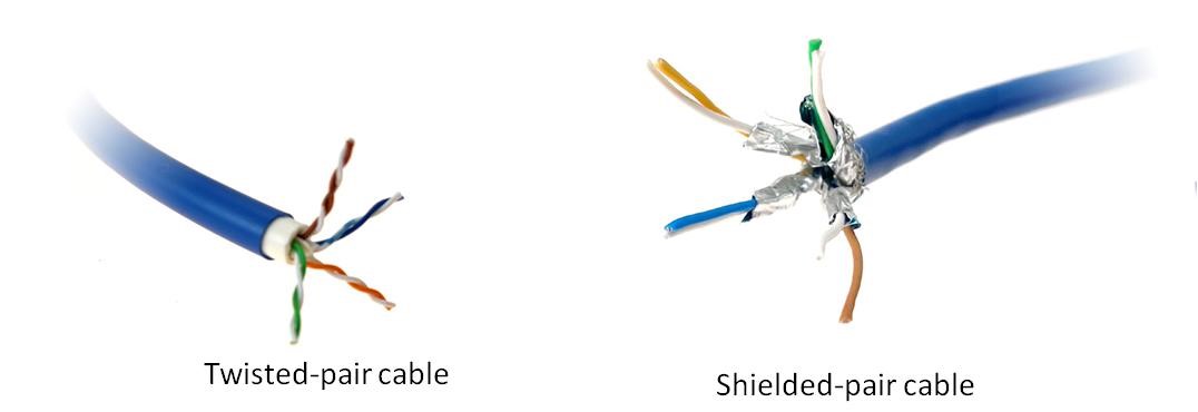
Unshielded twisted-pair (UTP) cables, shown in below Figure(Left), consist of twisted wire pairs without additional shielding, making them cost-effective, flexible, and easy to install, though they provide less protection against electromagnetic interference (EMI) and alien crosstalk.
In contrast, shielded twisted-pair (STP) cables, depicted in Figure(Right), feature an added layer of protection in the form of a foil or braided screen around the wire pairs, offering enhanced defense against EMI and alien crosstalk. This shielding, however, can increase the overall diameter of the cable, affecting its flexibility and ease of installation, with variations depending on the manufacturer.
Despite this, STP cables significantly improve signal integrity and performance in environments with high levels of electromagnetic interference, making them suitable for electrically noisy settings.
Classes and Categories of Twisted-Pair Cables
Twisted-Pair Cables Classes
Requirements for bandwidth are constantly increasing. New categories of cables are developed to support the higher frequencies required and to protect signals from electromagnetic interference.
- Standards:
>> International ISO/IEC 11801 Standard: One of the two main standards that stipulate the division of twisted-pair categories and classes.
>> American TIA/EIA-568B Standard: The other main standard for the division of twisted-pair categories and classes. - Backward Compatibility: One of the main benefits of twisted-pair copper cables is that newer categories are backward compatible, providing better total cost of ownership and easy upgrades.
- High-Bandwidth Support: Newer categories of twisted-pair cables can support high-bandwidth standards.
- Cost and Flexibility: These newer cables are more costly and less flexible, which can impact their use throughout a network.
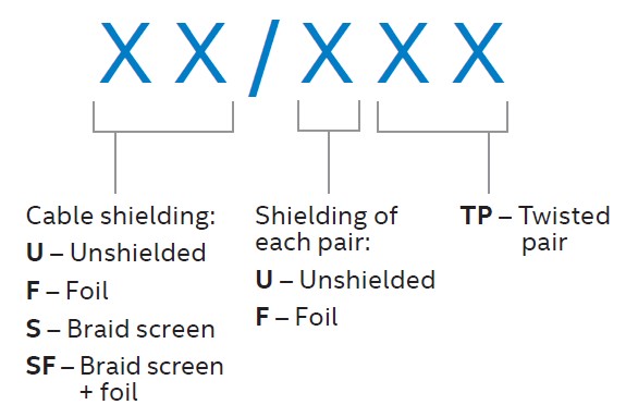
The shielding types have clearly defined markings recognized by the international TIA/EIA-568B Standard. A special code, as shown in below Figure, designates the type of cable.
Twisted-Pair Cables Categories
The EIA (Electronic Industry Association) has established standards of twisted-pair cable as below.
• Cat 1, 2, 3, 4, 5 are outdated and not used in any modern LAN network.
• Cat 5e, Cat 6, Cat 6a are the commonly used twisted-pair cables.
• Cat 7 is still a new technology and not commonly used.
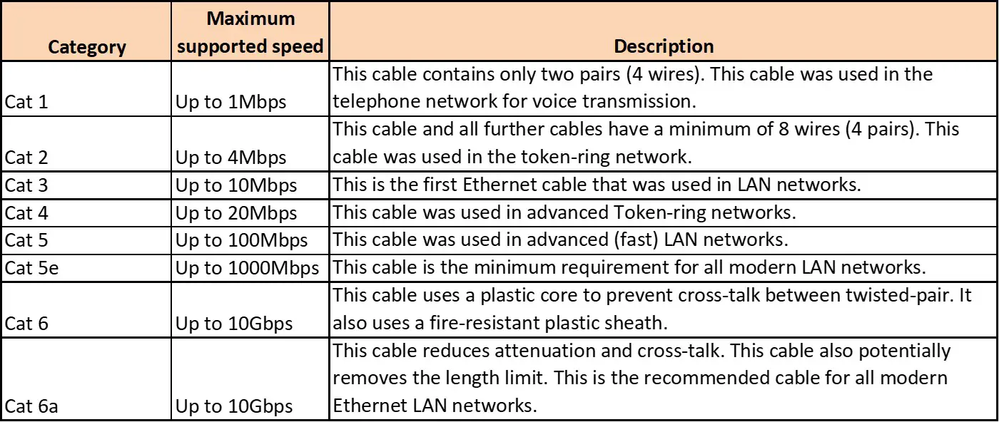
Commonly Used Networking Cable Categories
Category 5e (CAT5e) standard cables are defined in TIA/EIA-586 and are available in three types. Each cable type uses 1.5—two twists of pairs per centimeter of cable:
• UTP – Unshielded twisted pairs—pairs of conductors without additional protection of the cable from interference
• F/UTP – Foil shielded with unshielded twisted pairs—where the whole cable has an additional foil shield and the individual pairs of conductors are unshielded
• U/FTP – Unshielded with shielded twisted pairs—where only the pairs of conductors are foil shielded
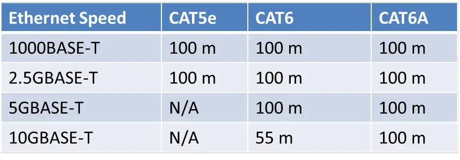
The Category 6 (CAT6) standard provides the same levels of additional shielding as CAT5e with the main difference being the number of twists per centimeter in the conductor pairs. According to the TIA/EIA-568B standard, CAT6 cables must have two or more twists for each centimeter and may additionally include a nylon spline to reduce crosstalk between pairs. This type of cable can provide 10GBASE-T connectivity but is limited to 55 meters.
Category 6A (CAT6A) provides the same shielding configurations as the previous categories and includes S/FTP, a braided shielding outer layer, and foil shielding for each twisted pair of conductors. This type of protection allows 10GBASE-T connectivity over a full 100 meters. Below table shows the types of BASE-T cables and maximum distances for each.
T568A and T568B Cable color codes
T568A and T568B are the color codes used for wiring eight-position RJ45 modular plugs. Both are allowed under the ANSI/TIA-568.2-D wiring standards.
• The T568A wiring pattern is recognized as the preferred wiring pattern for this standard, because it provides backward compatibility to both one-pair and two-pair USOC wiring schemes. The U.S. government requires the use of the preferred T568A standard for wiring done under federal contracts.
• The T568B standard matches the older AT&T 258A color code and has been the more widely used wiring scheme. It is also permitted by the ANSI/TIA-568.2-D standard, but it provides only single-pair backward compatibility to the USOC wiring scheme.
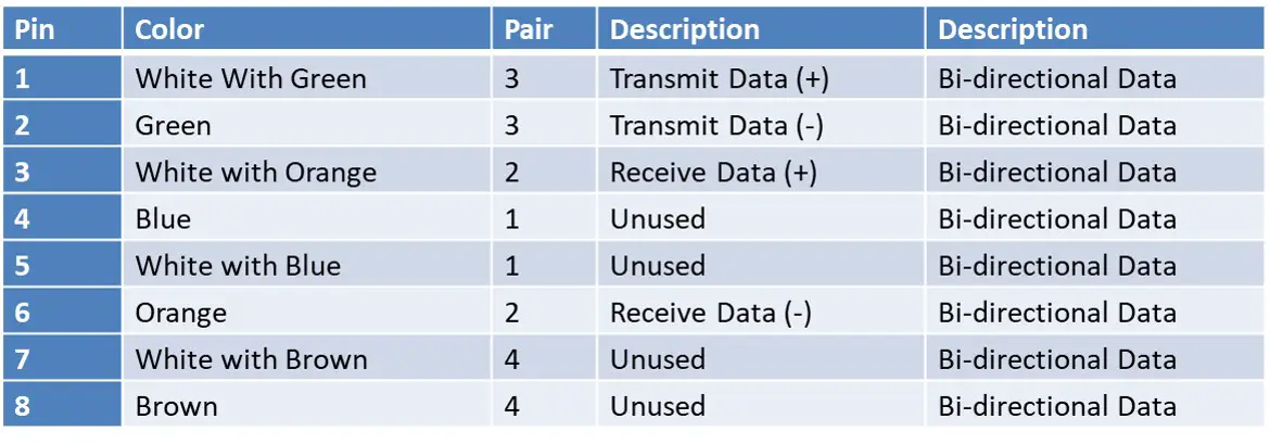
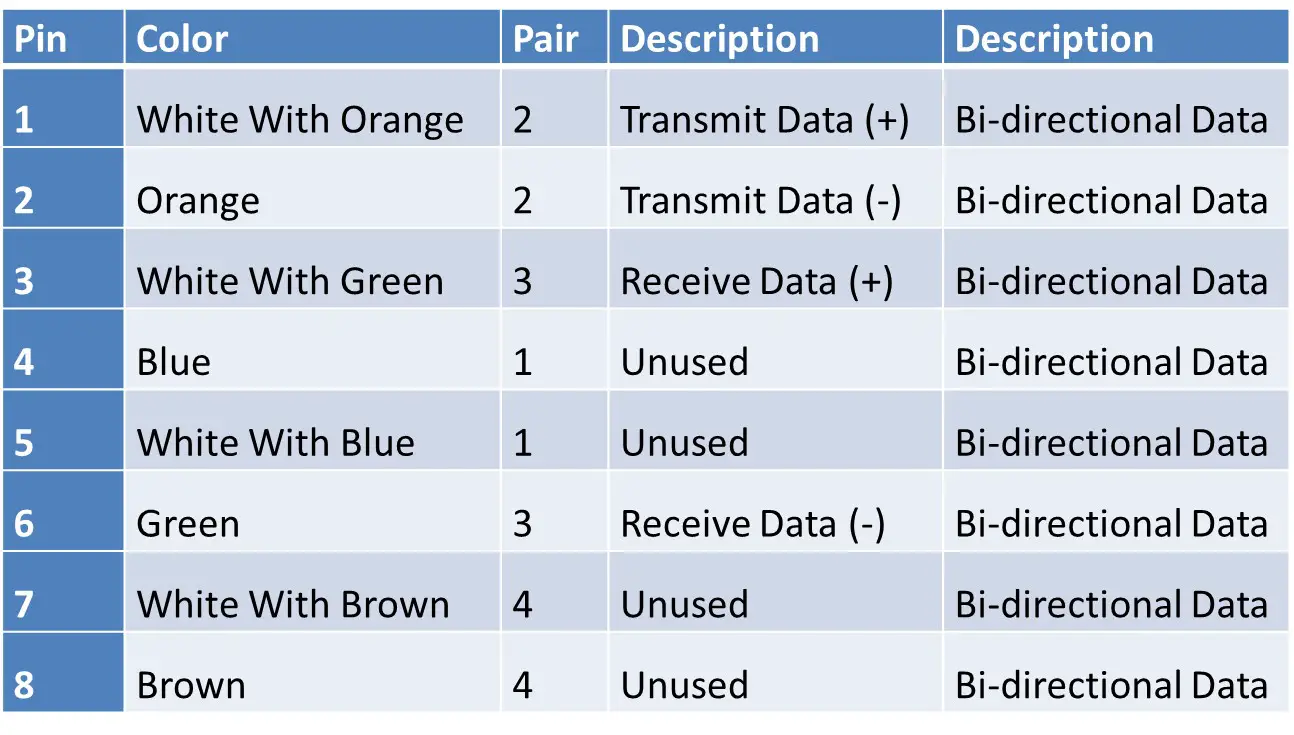
In Gigabit Ethernet, all four pairs of wires are used for transmitting and receiving data, allowing for higher speeds. In 10/100 Mbps Ethernet, only two pairs are used, with one pair dedicated to transmitting data and the other to receiving data. Here is the Ethernet cable pin-out for 10/100 Mbps and Gigabit Ethernet:
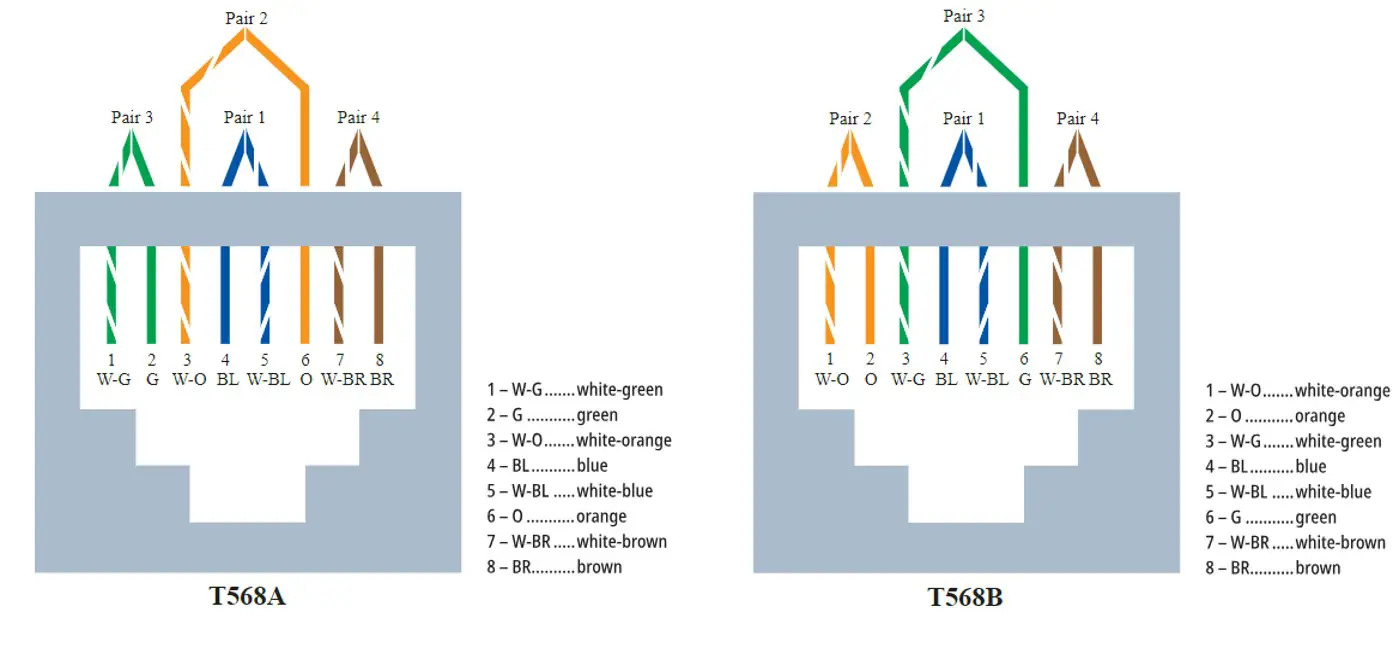
T568A Pin-out (Performed)
T568B Pin-out (Performed)
Straight-through and Crossover Cable
The picture below shows the cable connection between two network devices. The connection can be either straight-through or crossover, depending on the types of devices being connected at both ends. A straight-through cable is used when different types of devices need to be connected at both ends of the cable, whereas a crossover cable is used when the same types of devices need to be connected at both ends of the cable.
Straight-through Cable
The straight-through cables, also called a patch cable have identical ends and are used for connecting computers through a hub/switch. This type of cable is typically used to connect different types of devices, such as:
• Connect a computer to a switch/hub’s normal port.
• Connect a computer to a cable/DSL modem’s LAN port.
• Connect a router’s WAN port to a cable/DSL modem’s LAN port.
• Connect a router’s LAN port to a switch/hub’s uplink port. (normally used for expanding network)
• Connect 2 switches/hubs with one of the switch/hub using an uplink port and the other one using normal port.
• Uplink port special port that eliminates the need of crossovercable.
Crossover Cable
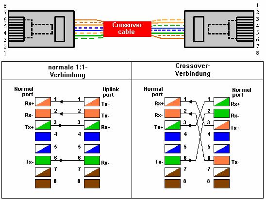
A crossover cable is required for direct connection between two devices (e.g., server and client connection) without a switch. Below figure shows the pin and color description of the normal cable as well as the crossover cable. With these
colors, it is easy to distinguish between normal and crossover cable. For instance, a direct connection between two PCs (or some connections of Hubs) requires a crossover cable. The wires are crossed, so a transfer interface can reach the receive interface, and vice versa.
• Used to connect same type of devices without a switch or hub.
>> Connect 2 computers directly
>> Connect a router’s LAN port to a switch/hub’s normal port (normally used for expanding network)
>> Connect 2 switches/hubs by using normal port in both switches/hubs
The pin-out for a crossover cable is shown below.
|
Pin (T568A) |
Color (T568A) |
Pin (T568B) |
Color (T568B) |
|
1 |
White/Green |
1 |
White/Orange |
|
2 |
Green |
2 |
Orange |
|
3 |
White/Orange |
3 |
White/Green |
|
4 |
Blue |
4 |
Blue |
|
5 |
White/Blue |
5 |
White/Blue |
|
6 |
Orange |
6 |
Green |
|
7 |
White/Brown |
7 |
White/Brown |
|
8 |
Brown |
8 |
Brown |
Summary
Twisted-pair Ethernet cables are essential for networking, featuring internal wire pairs twisted together to reduce electromagnetic interference (EMI) and crosstalk. There are two main types:
• Unshielded Twisted-Pair (UTP): Affordable, flexible, and easy to install, but offers less protection against EMI and crosstalk.
• Shielded Twisted-Pair (STP): Includes additional shielding (foil or braided) for enhanced EMI protection, suitable for noisy environments.
• Categories of Twisted-Pair Cables:
– Categories range from outdated Cat 1-5 to modern Cat 5e, Cat 6, and Cat 6A.
– Higher categories support increased bandwidth and better EMI protection.
– Commonly used are Cat 5e (1 Gbps), Cat 6 (up to 10 Gbps over shorter distances), and Cat 6A (up to 10 Gbps over 100 meters).
• Ethernet Cable Pin-outs:
– T568A and T568B standards define wiring patterns for Ethernet cables.
– Used for 10/100 Mbps and Gigabit Ethernet connections, each pin serves specific data transmission roles.
• Straight-through vs. Crossover Cables:
– Straight-through**: Used for connecting different devices (e.g., computer to switch).
– Crossover: Used for direct connection between similar devices (e.g., computer to computer).
• These cables are crucial for maintaining signal integrity and supporting high-speed data transfer in networking and telecommunications.
Author Profile
- 20+ years embedded hardware design professional with a burning passion for teaching. Sharing the intricate world of embedded hardware is my mission and joy.
Latest entries
 Tech Updates12 October 2024Explore the Wireless Connectivity With NXP’s FRDM-RW612 Development Board
 USB6 October 2024USB 2.0 Standard Explained
 USB20 September 2024USB – (Universal Serial Bus) Overview, Purpose, Standards and Types
 Tech Updates8 September 2024Renesas Introduces the RRH62000- A Game-Changer in Indoor Air Quality Monitoring
