Selecting magnetics for Ethernet, especially for interfaces like 10/100Base-T or 1000Base-T (Gigabit Ethernet), involves considering several key factors. Magnetics offers a straightforward solution to many functions of this interface, including electrical isolation, signal balancing, common mode rejection, impedance matching, and EMC improvement. Here’s a guide to help you select the right magnetics for your Ethernet application.
Part of Magnetics & It’s Requirements
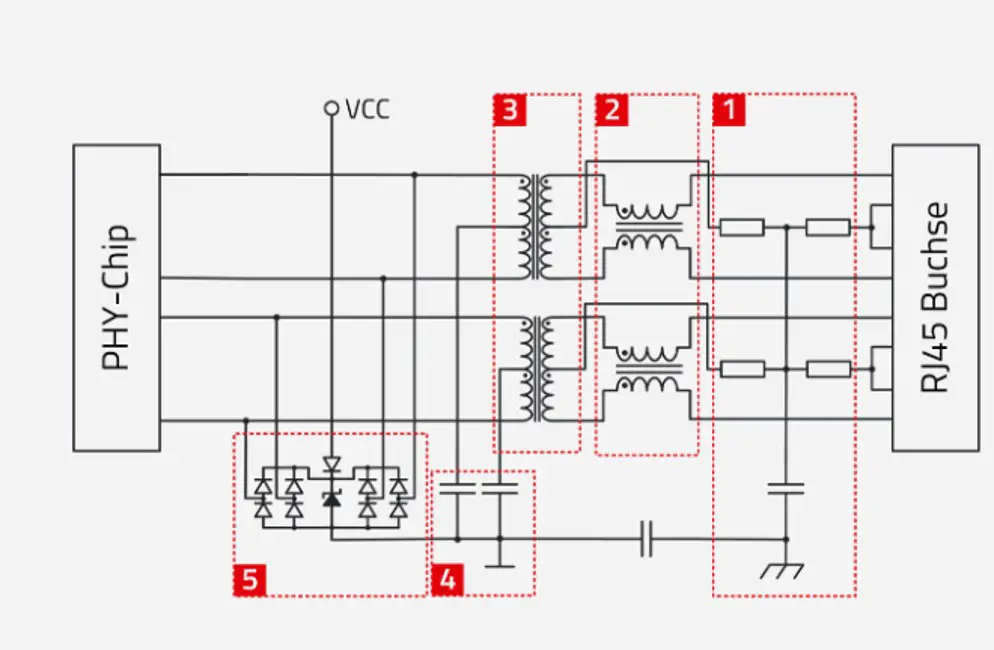
Modern integrated RJ45 LAN connector generally keeps Part 1, 2, 3 and 4 & ESD diodes are kept on PCB.
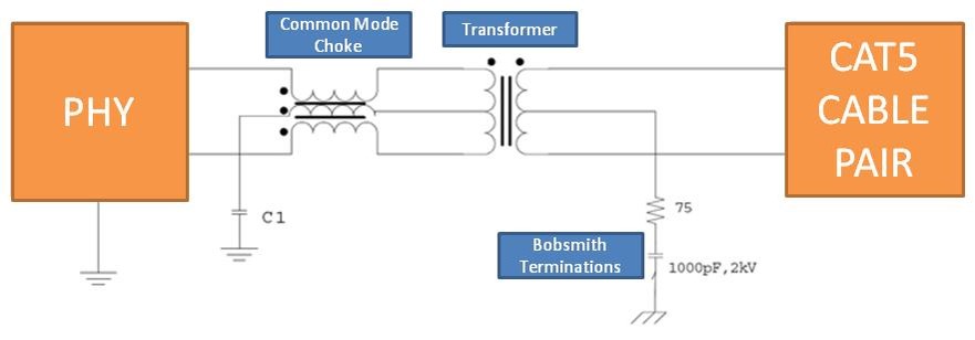
- Bob Smith Termination: To reduce common mode current and susceptibility to interference from unused wire pairs on the RJ45 connector
- Common Mode Chokes: Improve EMC by attenuating common-mode interference
- Signal Transformer: Provides galvanic isolation between PHY chip and RJ45 jack, protects against transients, and matches the impedance to the internal logic and to balanced wire pairs
- 4MLCC Capacitors: Contribute to common mode rejection by RF-connecting the center taps of the transformers to ground (GND)
- TVS-Dioden-Array: Limits interface transients to the PHY against GND.
Parameters for Selecting the Right Magnetics
When selecting a LAN magnetics module, it’s essential to consider the specific requirements of the PHY (Physical Layer Device) chip in your design. Aside from the PHY chip’s specifications, you should also compare various performance parameters of the magnetics module to ensure optimal compatibility and performance. Here are some of the key performance values to consider:
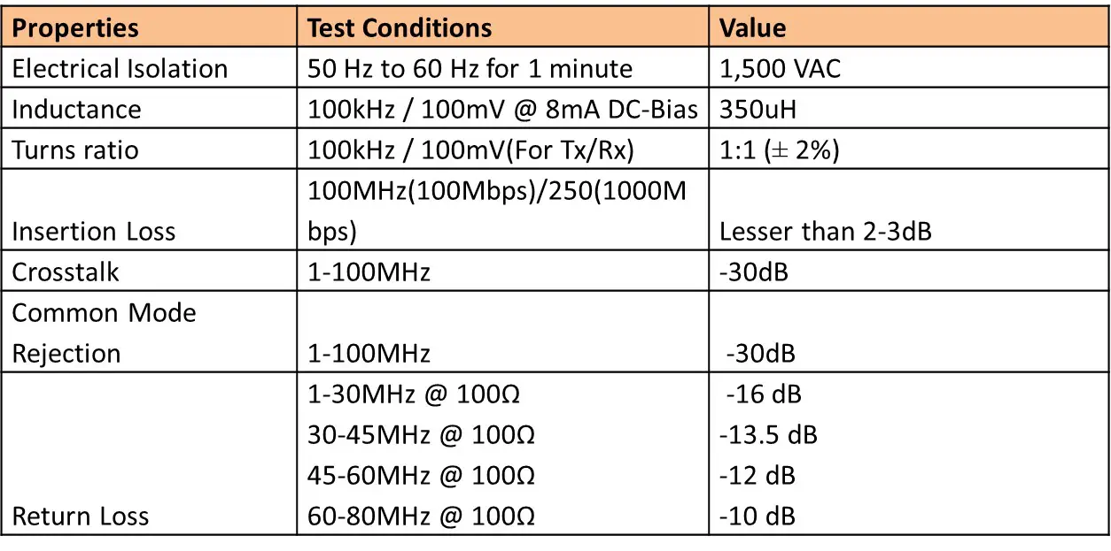
Insertion Loss
- Insertion loss refers to the loss of signal power that occurs when the magnetics module is inserted into the signal path. Lower insertion loss is generally preferred as it ensures better signal integrity.
- Compare the insertion loss at different frequencies (e.g., 100 MHz for 100Base-T, 250 MHz for 1000Base-T) to ensure it meets the PHY’s requirements and the Ethernet standard (Lesser than 2-3dB).
Return Loss
- Return loss measures how much of the signal is reflected back toward the source due to impedance mismatches. Higher return loss values indicate better impedance matching and less signal reflection.
- The IEEE 802.3 standard, paragraph 40.8.3.1, specifies the following requirements for differential impedance at the MDI (Medium Dependent Interface):
- Balanced Cabling Impedance: The differential impedance must match balanced cabling with an impedance of 100 Ω ± 15%.
- Return Loss Requirement: The reflection due to differential signals incident upon the MDI must be attenuated relative to the incident signal by:
- At least 16 dB over the frequency range of 1.0 MHz to 40 MHz.
- At least 10 – 20log(f/80) dB over the frequency range of 40 MHz to 100 MHz (where f is in MHz
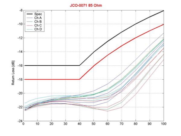
There are two key points to emphasize about the above return loss plot:
- For a real system with output impedance contributions from both PHY output and a magnetic transformer to satisfy the IEEE specification, magnetics with a return loss margin of at least 2 dB (versus the IEEE 802.3 specification at the MDI) are recommended. The red curve in the plot reflects a 2 dB back-off from the IEEE 802.3 limit.
- The measured return loss is flat to within 3 dB up to 40 MHz–50 MHz. That flatness is a key aspect in maintaining signal integrity.
Common-Mode Rejection Ratio (CMRR)
CMRR is a measure of how effectively the magnetics module suppresses common-mode noise. A higher CMRR value indicates better noise rejection, which is crucial for reducing EMI and ensuring signal integrity.
- Look for a magnetics module with a high CMRR, especially if your application is in a noisy environment or needs to meet stringent EMI requirements.
- Transformers provide a simple and effective means to establish a balanced connection to each ethernet cable pair & reject common-mode signals.
- Common-Mode Rejection in Transformers functions in both directions of a port, attenuating common-mode signals:
- From Cable to PHY: Reduces noise picked up by the cable from its environment.
- From PHY to Cable: Reduces noise originating from the PHY and its surrounding system.
- Benefits of Common-Mode Attenuation
- Improved Signal-to-Noise Ratio: Reduces common-mode signals picked up by the cable, improving the system’s signal-to-noise ratio.
- Enhances the PHY’s ability to recover the data signal, aiding in achieving the desired bit error rate (BER).
- Enhanced EMC Performance
- Noise from board circuits can couple to the signal traces from the PHY to the magnetics, often as common-mode noise.
- This common-mode noise is attenuated by the magnetics, improving electromagnetic compatibility (EMC) performance.
- Reduced Radiated Noise:
- Since 10/100/1000BASE-T uses unshielded twisted pair cables, any common-mode noise that passes through the magnetics and onto the cables will radiate.
- Magnetics help reduce this radiated noise by attenuating common-mode signals.
Isolation Voltage
- The isolation voltage indicates the maximum voltage the magnetics module can withstand between the PHY side and the network side without breaking down.
- IEEE specification requires a 10/100/1000BASE-T port to be able to withstand 1,500 VAC at 50 Hz to 60 Hz for 1 minute between ports or from each port to the chassis ground.
Magnetic Types
Several different magnetic types are available, all conforming IEEE requirements. Only those containing a common-mode choke (CMC) are described in the document.
They can be split into two groups:
- 12-core magnetics that consist of transformer, a common mode choke, and an autotransformer,
- 8-core magnetics that consist of a transformer and a common mode choke.
- Their advantages and disadvantages are described below.
12-core magnetics that consist of transformer
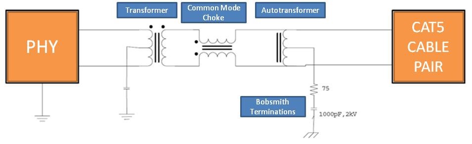
- Transformer with 1:1 Ratio:
- Purpose: Creates galvanic isolation between the Ethernet cable and the system.
- Connection: The center tap of the transformer on the PHY side should be connected to ground through a capacitor.
- Common-Mode Choke (CMC): Attenuation of Common-Mode Noise
- From the System: The CMC reduces electromagnetic emissions by filtering the signal, helping to improve the overall system’s EMC performance.
- From the Outside: The CMC enhances electromagnetic immunity by attenuating external common-mode noise that enters through the twisted pair.
- Autotransformer Characteristics:
- High Impedance to Differential Signals: The autotransformer presents high impedance to differential signals in the twisted pair, making it effectively “invisible” to these signals.
- Low Impedance to Common-Mode Currents: The autotransformer presents low impedance to common-mode currents, allowing these currents to flow to a circuit known as the Bob Smith termination.
8-core magnetics that consist of transformer
- Components: Includes a transformer and a Common-Mode Choke (CMC).
- Cable Side: CMC is placed on the cable side of the transformer.
- PHY Side: CMC is placed on the PHY side of the transformer (as shown in different figures).
- Advantages of Placing CMC on the Cable Side:
- Reduces common-mode noise generated by the center taps of the transformer.
- Reduces noise due to transformer winding imbalance.
- Filters noise in systems where the chassis ground is connected to the digital ground (common in computer motherboards).
- Even if connected to Earth ground through the power supply, it can still filter noise that may be injected through the high voltage capacitor.
- Removing the capacitor may improve EMC performance in such cases.
- Disadvantage of Cable-Side CMC Placement:
- The high impedance introduced by the CMC between the cable and the impedance-matching resistor reduces the effectiveness of the Bob Smith termination for common-mode noise.
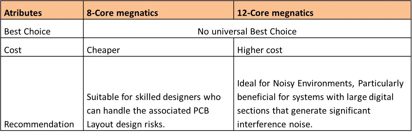
- 8-Core Versus 12-Core magnetics
Integrated Versus Discrete RJ-45 Jacks
To minimize component count and product size, some manufacturers offer magnetic modules where the magnetic block is integrated into the RJ45 connector. This approach has both advantages and disadvantages.
- Advantages of Integrated Magnetics:
- Lower Component Count: Fewer components lead to reduced production and assembly costs.
- Reliability is improved as there are fewer solder connections in the design.
- Enhanced EMC Shielding: The metal shield around the integrated module provides better shielding for the sensitive cable-side signals.
- Smaller Footprint: The integrated design occupies less space compared to using separate magnetics and connectors.
- Disadvantages of Integrated Magnetics:
- Difficult Rework: If a magnetic or connector fails during production testing, it’s harder and costlier to rework or replace.
- Performance Trade-offs:
- Smaller Magnetic Cores: Due to space constraints, the cores are smaller and placed closer together, which can degrade crosstalk and EMC characteristics, and increase nonlinear distortion and losses.
- Variable EMC Performance: The electromagnetic emission performance may vary depending on the specific product, with the possibility of either better or worse outcomes.
- Risk of Noise Coupling: The small size of the magnetic part increases the risk of noise coupling between the cable side and the PHY side, limiting the effectiveness of the common-mode choke.
- Advantages of Discrete Magnetics:
- Better Common-Mode Filtering: Separate magnetics and connectors have lower coupling between different parts, resulting in superior common-mode noise filtering.
- Improved Performance: The larger magnetic cores used in discrete magnetics offer better overall performance, especially in terms of electromagnetic compatibility (EMC).
- Disadvantages of Discrete Magnetics:
- Potential for EMC Issues: After filtering by the magnetics, the signals are routed to the connector on the PCB. If the system box contains noisy logic, this noise can couple to these lines and create EMC problems.
Choosing Between Integrated and Discrete RJ-45 Jacks
Considerations:
- Design Complexity: For simpler designs or where space is at a premium, integrated jacks may be preferable. For complex systems with high noise environments, discrete jacks might offer better performance.
- Performance Requirements: Evaluate the need for superior common-mode noise filtering and signal integrity. Discrete solutions typically provide better performance but at the cost of increased size and component count.
- Production Costs: Integrated jacks can reduce overall component count and potentially lower assembly costs, whereas discrete solutions may increase costs but provide better performance.
Magnetics for Current Mode & Voltage Mode Ethernet PHY
Ethernet PHY transceivers generally fall into two main architectural categories:
- Current Mode Line Driver PHYs
- Voltage Mode Line Driver PHYs
Current Mode Line Driver PHY
The current mode driver pulls a constant current from a voltage source (e.g., 2.5V, 1.8V, or other levels) based on the required current for the line driver as shown in below picture.
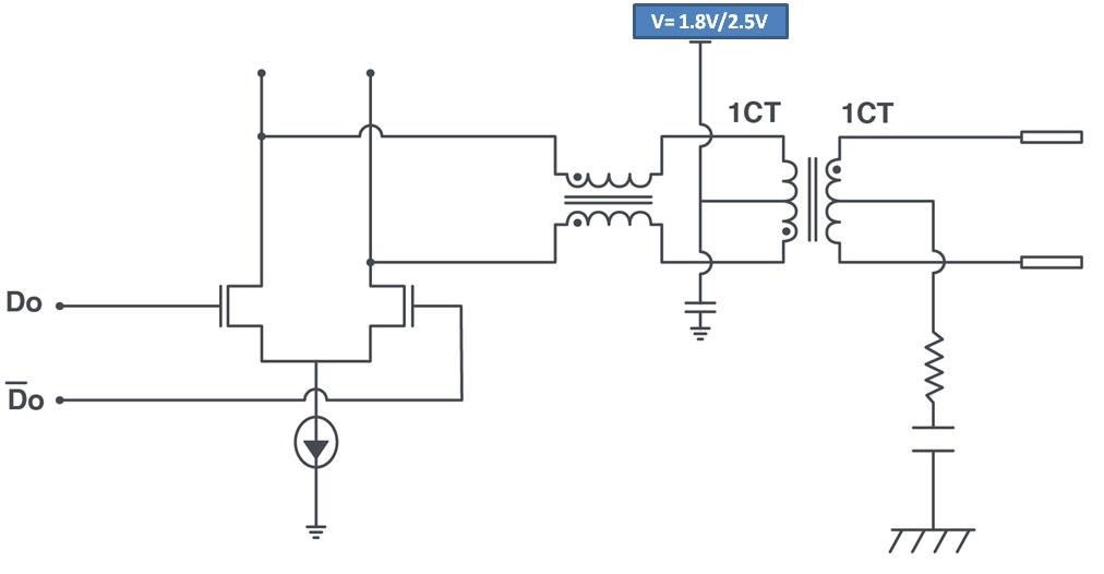
- EMI Issues: Typically associated with Differential Mode interference.
- Power Dissipation: Higher power dissipation compared to voltage mode line drivers, which can be a drawback in energy-sensitive designs.
- Usage: Despite higher power dissipation, current mode line drivers are often favored by LAN PHY manufacturers due to their simpler design and lower cost.
- Design Implications:
- Simplicity and Cost: Offers a simpler and more cost-effective design but with higher power dissipation.
- Magnetics Design: Requires careful consideration of differential mode interference, making it crucial to select magnetics that can handle these EMI challenges effectively.
Voltage Mode Line Driver PHY
Voltage Mode Line Driver PHYs utilizes available 3.3V power supplies within the system, eliminating the need for a separate voltage source connected to the transformer’s center tap. Below configuration shows Voltage Mode Line Driver PHYs
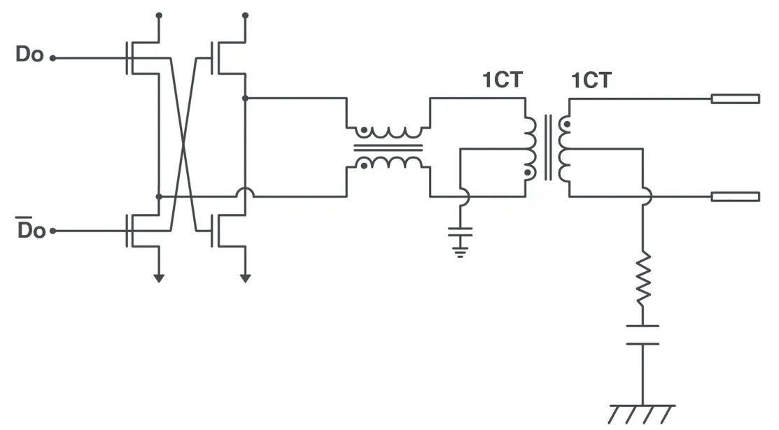
- EMI Issues: Primarily related to Common Mode interference.
- Common Mode Noise Management: Without the current pulled through the center tap, a two-wire Common Mode Choke (CMC) effectively provides high impedance to limit Common Mode noise.
- Ground Noise Filtering: On noisy boards, ground noise may be injected into the system through the transformer’s center tap. To address this, Bel’s proprietary three-wire CMC design is used to filter ground noise from the system board.
- Design Implications:
- Energy Efficiency: Typically the preferred choice for new PHY designs due to lower power dissipation.
- Magnetics Design: Magnetics for voltage mode drivers should focus on mitigating common mode noise, especially in environments with high levels of ground noise. Bel’s patented three-wire CMC can be particularly effective in such cases.
Choosing between voltage mode and current mode line driver PHYs involves balancing design simplicity, cost, power efficiency, and EMI management. While current mode drivers are popular for their simplicity and lower cost, voltage mode drivers are often preferred in new designs for their better energy efficiency and noise management capabilities. The selection of appropriate magnetics is critical in addressing the specific EMI challenges associated with each PHY architecture.
Operating Temperature Range
- The temperature range within which the magnetics module can operate reliably. Typically magnetics module available in temperate range of -40°C – + 85°C/0°C – +70°C.
- Ensure the operating temperature range meets the environmental conditions of your application. For industrial or automotive applications, a wider temperature range is typically required.
Summary:
When selecting magnetics for Ethernet interfaces like 10/100Base-T or 1000Base-T, it’s essential to consider factors such as electrical isolation, signal integrity, EMI (Electromagnetic Interference) management, and compatibility with the PHY (Physical Layer Device) chip.
Key Components of Magnetics:
- Bob Smith Termination: Reduces common mode interference from unused RJ45 wire pairs.
- Common Mode Chokes (CMC): Improves EMC by attenuating common-mode interference.
- Signal Transformer: Provides galvanic isolation, transient protection, and impedance matching.
- MLCC Capacitors: Contribute to common mode rejection by grounding the center taps of transformers.
- TVS-Diode Array: Protects the PHY against transients.
Critical Parameters for Magnetics Selection:
- Electrical Isolation: Ensures the magnetics module can withstand high voltages (e.g., 1,500 VAC for 1 minute).
- Insertion Loss: Lower insertion loss indicates better signal integrity.
- Return Loss: Higher return loss values indicate better impedance matching, reducing signal reflection.
- Common-Mode Rejection Ratio (CMRR): Higher CMRR values improve noise rejection and overall EMC performance.
- Operating Temperature Range: Ensure compatibility with the environmental conditions of your application.
Magnetic Types:
- 12-Core Magnetics: Provides better common-mode filtering and is ideal for noisy environments but comes with a higher cost.
- 8-Core Magnetics: More cost-effective but may require skilled designers to handle associated risks.
Integrated vs. Discrete RJ-45 Jacks:
- Integrated Magnetics: Lower component count, reduced production cost, and smaller footprint but harder to rework and may have variable EMC performance.
- Discrete Magnetics: Offers better performance, particularly in noisy environments, but increases component count and size.
Magnetics for Current Mode vs. Voltage Mode PHYs:
- Current Mode PHY: Simpler and lower-cost design with higher power dissipation, typically associated with differential mode interference.
- Voltage Mode PHY: Preferred for new designs due to lower power dissipation, with a focus on common-mode noise management.
Selecting the right magnetics involves balancing design simplicity, cost, performance, and EMI management, tailored to the specific requirements of your Ethernet application.
Author Profile
- 20+ years embedded hardware design professional with a burning passion for teaching. Sharing the intricate world of embedded hardware is my mission and joy.
Latest entries
 Tech Updates30 November 2025STM32WBA6: The Next-Generation MCU Powering Secure Short-Range Wireless Designs
 Blogs24 November 2025High-Speed PCB Layout Design Guide-104
 Tech Updates14 September 2025Renesas Launches RL78/L23 Ultra-Low-Power MCUs to Power Smarter Home Appliances
 Blogs7 September 2025High-Speed PCB Layout Design Guide-103


