For an electronics design engineer understanding the capacitors is very important because capacitors stand as pillar components that hold central significance across a spectrum of electronics devices.
In the forthcoming sections of this blog, We’ll explain the behavior of capacitors in series and parallel with the help of a few good examples, and uncover the fundamental principles governing their operations. At the end of this blog post, you will understand why capacitor is so important to a hardware designer.
What is a Capacitor?
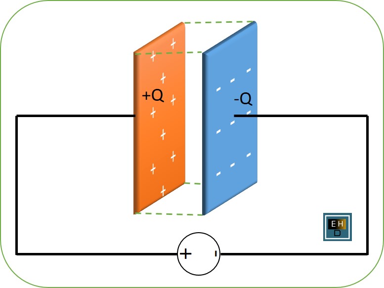
A capacitor is an electronic component that stores and releases electrical energy. It consists of two conductive plates separated by an insulating material called a dielectric. When a voltage is applied across the plates, positive charges accumulate on one plate while negative charges accumulate on the other plate.
Capacitors are commonly used in electronic circuits for various purposes. They can store electrical energy and release it when needed, acting as temporary power sources or energy reservoirs. Capacitors can also filter out unwanted noise or stabilize voltage levels in circuits. Capacitors are commonly used in electronic circuits for various purposes, including energy storage, filtering, and timing.
The capacitance of a capacitor determines its ability to store charge. It is measured in farads (F), although most capacitors used in everyday electronics have capacitances ranging from picofarads (pF) to microfarads (µF).
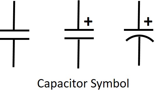
Symbol of Capacitor
How to Calculate Capacitors in Series and Parallel?
Here is the detailed explanation to understand the capacitors in Series and Parallel with the help of some basic examples.
Capacitor in Series
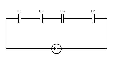
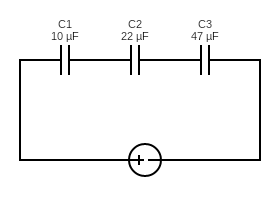
In a series connection, capacitors are connected end-to-end, forming a single path for the flow of current. To calculate the total capacitance in a series circuit, you need to use the reciprocal formula.
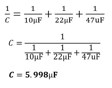
Simply put, you take the reciprocal of each capacitor’s value and add them together. The equivalent capacitance (C) can be calculated as:
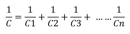
Where C1, C2, and C3 represent the individual capacitance values.
For examples
In the below circuit, two capacitors C1=10µF, C2= 22µF, and C3=47uF are connected in series hence the equivalent capacitance C could be calculated as:
 Capacitor in Parallel
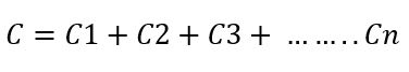
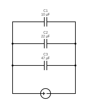
On the other hand, in parallel connection, capacitors are connected side by side with each other. The total capacitance in a parallel circuit is simply the sum of all individual capacitances. You can add up all the capacitance values to find the total equivalent capacitance (C) in a parallel circuit can be calculated as:
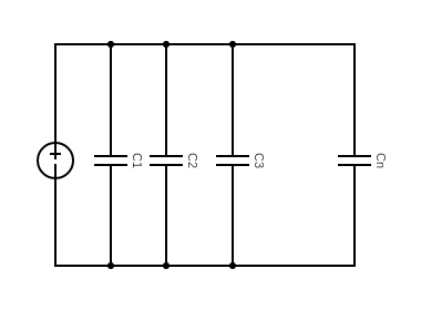
For examples
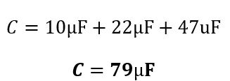
In the below circuit, two capacitors C1=10µF, C2= 22µF, and C3=47uF are connected in parallel hence the equivalent capacitance C could be calculated as:
How Does a Capacitor Work?
The working principle of a capacitor lies in its ability to store charge. When a voltage is initially applied, electrons from the negative plate are attracted to the positive plate, creating an electric field between them. This process continues until the potential difference across the plates equals the applied voltage.
The basic working principle of a capacitor can be explained using the formula for the capacitance (C) of a capacitor:
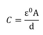
Where:
- C is the capacitance of the capacitor (measured in farads, F).
- ε₀ (epsilon naught) is the permittivity of the dielectric material between the plates (measured in farads per meter, F/m).
- A is the area of one of the capacitor plates (measured in square meters, m²).
- d is the distance between the plates (measured in meters, m).
By going through the below steps you can understand how does a capacitor works:
-
Charging
When you connect a voltage source (like a battery or DC source) to the terminals of a capacitor, it starts to charge. Electrons from the negative terminal of the voltage source flow onto one of the capacitor plates, while an equal number of electrons are drawn away from the other plate. This process continues until the voltage across the c When a capacitor charges and discharges in an RC (resistor-capacitor) circuit, the voltage across the capacitor as a function of time follows distinct exponential curves. These curves are characterized by a time constant (τ), which is the product of the resistance (R) and capacitance (C) in the circuit. Here are the charging and discharging graphs for a capacitor in an RC circuit:
During charging, the voltage across the capacitor (Vc) starts at zero and increases exponentially toward the source voltage (Vs) as the capacitor accumulates charge. The equation describing the charging process is:
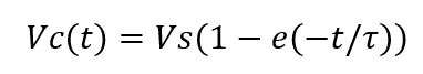
Where:
- Vc(t) is the voltage across the capacitor at time t.
- Vs is the source voltage.
- τ is the time constant, τ=R∗C.
- e is the base of the natural logarithm, approximately 2.71828.
As time (t) approaches infinity, the voltage across the capacitor (Vc) approaches the source voltage (Vs).
-
Electric Field Formation
As the charge accumulates on the plates, an electric field forms between them. This field is created by the attraction of the positive charge on one plate to the negative charge on the other plate. The electric field stores energy in the form of electric potential energy.
-
Energy Storage
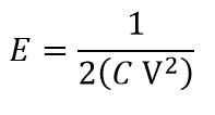
The amount of energy stored in the capacitor is directly proportional to the capacitance (C) and the square of the voltage (V) across the capacitor:
Where:
- E is the energy stored (measured in joules, J).
- C is the capacitance of the capacitor (in farads, F).
- V is the voltage across the capacitor (in volts, V).
-
Discharging
When you disconnect the voltage source, the capacitor can discharge by releasing the stored energy. This energy can be used to power a circuit or perform work.
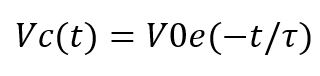
During discharging, the voltage across the capacitor starts at its initial value (V0), typically the source voltage (Vs) after charging, and decreases exponentially toward zero as the stored energy is discharged through the resistor. The equation describing the discharging process is:
Where:
- Vc(t) is the voltage across the capacitor at time t.
- V0 is the initial voltage across the capacitor (source voltage).
- τ is the time constant, τ=R∗C.
- e is the base of the natural logarithm.
As time (t) approaches infinity, the voltage across the capacitor (Vc) approaches zero.
Capacitors are often used in circuits to store energy temporarily, smooth out voltage fluctuations (filtering), and control the timing of electrical signals. They are also crucial components in electronic devices like radios, amplifiers, and power supplies, where they serve various functions based on their capacitance values and dielectric materials.
Application of Capacitors
Capacitors are versatile electronic components that find applications in a wide range of industries and devices. They store and release electrical energy, making them essential in various electrical circuits. Let’s explore some common applications of capacitors.
- Power Supply Filtering: Capacitors are used in power supply circuits to filter out noise and stabilize the voltage. They smooth out the ripples and fluctuations in the power source, ensuring a steady and clean supply of electricity.
- Motor Starters: Capacitors play a crucial role in motor starting circuits. They provide an initial surge of power to start electric motors efficiently, especially in devices like air conditioners, refrigerators, and washing machines.
- Energy Storage: Capacitors can store electrical energy for short periods of time. This property is utilized in flash cameras, where capacitors quickly discharge to produce a bright flash of light for capturing photographs.
- Timing Circuits: Capacitors are used alongside resistors to create timing circuits or oscillators that generate precise time intervals or frequencies. These circuits are commonly found in electronic clocks, timers, and frequency generators.
- Signal Coupling: In audio systems or amplifiers, capacitors are employed for coupling signals between different stages or components while blocking any DC (direct current) component present in the signal path.
- Power Factor Correction: Large capacitors are utilized for power factor correction to improve the efficiency of electrical systems by reducing reactive power consumption and optimizing the overall power factor.
- Electronic Filters: Different types of capacitors combined with resistors and/or inductors form filters that allow specific frequencies to pass through while attenuating others. These filters are extensively used in audio equipment, communication systems, and radio frequency applications.
These examples illustrate just a few applications of capacitors; their versatility makes them indispensable components across numerous industries such as electronics, telecommunications, automotive engineering, aerospace technology, and more.
One of the most common applications of capacitors is in power supply systems. They are used to smooth out voltage fluctuations and provide a stable source of power to electronic devices. Capacitors can also be found in audio systems, where they help filter out unwanted noise and improve sound quality.
Capacitors are essential components in many electronic circuits, such as timing circuits, oscillators, and filters. They play a crucial role in controlling the flow of current and voltage within these circuits.
Capacitors also find applications in motor start-up circuits, where they provide an initial surge of power to get the motor running smoothly. Additionally, they are used in electric vehicles to store regenerative braking energy for later use.
Key Points to Consider While Using the Capacitor in Any Circuit
Energy Storage: Capacitors can store electrical energy temporarily. The amount of energy a capacitor can store is directly proportional to its capacitance and the square of the voltage across it, as mentioned in the previous answer.
Dielectric Materials: The dielectric material between the plates of a capacitor plays a crucial role. Different dielectrics have different permittivity values, affecting the capacitance and other characteristics of the capacitor. Common dielectric materials include ceramics, electrolytic fluids, and plastics.
Polarized vs. Non-Polarized: Some capacitors are polarized, meaning they have a specific orientation and must be connected with the correct polarity to avoid damage. Electrolytic capacitors are a common type of polarized capacitor. In contrast, non-polarized capacitors can be connected in any direction.
Voltage Rating: Capacitors have voltage ratings that indicate the maximum voltage they can safely handle. Exceeding this voltage can lead to the breakdown of the dielectric and damage the capacitor.
Frequency Response: Capacitors have a frequency-dependent behavior. They can act as high-pass or low-pass filters depending on the frequency of the AC signal applied to them. This property is used in audio and signal processing applications.
Time Constants: Capacitors are used in conjunction with resistors to create time constants in circuits. The time constant (τ) of an RC circuit (resistor-capacitor) determines the rate at which the capacitor charges or discharges. It is equal to the product of the resistance (R) and capacitance (C).
Capacitor Discharge: When a charged capacitor is discharged through a resistor, it follows an exponential decay curve. The time it takes for the voltage across the capacitor to decrease to approximately 37% of its initial value is one time constant (τ).
Capacitor Aging: Over time, the characteristics of capacitors can change due to factors like temperature and voltage stress. This can lead to a decrease in capacitance or increased leakage current, affecting the performance of electronic circuits.
Varied Capacitance Values: Capacitors come in a wide range of capacitance values, from picofarads (pF) to farads (F). This wide range allows them to be used in various electronic applications, from tiny capacitors in microelectronics to large capacitors in power electronics.
Author Profile
- 20+ years embedded hardware design professional with a burning passion for teaching. Sharing the intricate world of embedded hardware is my mission and joy.
Latest entries
 Tech Updates30 November 2025STM32WBA6: The Next-Generation MCU Powering Secure Short-Range Wireless Designs
 Blogs24 November 2025High-Speed PCB Layout Design Guide-104
 Tech Updates14 September 2025Renesas Launches RL78/L23 Ultra-Low-Power MCUs to Power Smarter Home Appliances
 Blogs7 September 2025High-Speed PCB Layout Design Guide-103


