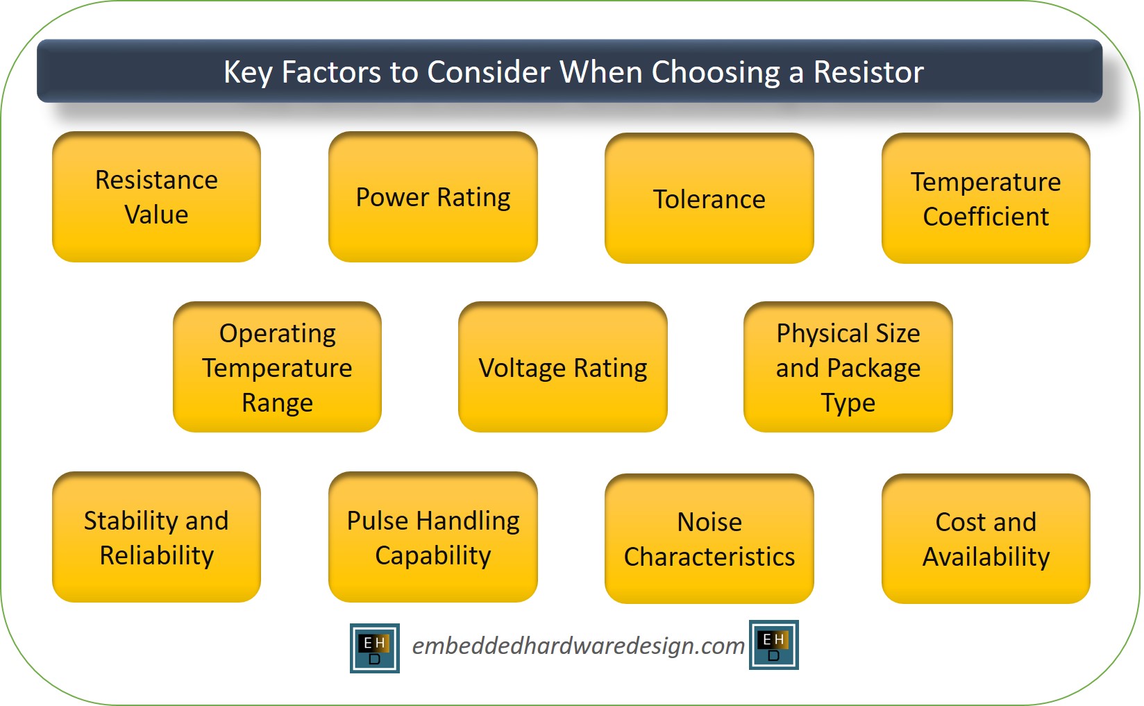
Selecting the appropriate resistor for a specific application requires considering various factors to ensure optimal performance and reliability. Here are the key factors to consider when choosing a resistor:
1- Resistance Value (Ohm, Ω)
The most fundamental characteristic of a resistor is its resistance value, which is measured in ohms (Ω). Ensure that the selected resistor has the precise resistance needed for the circuit to function as intended.
Example Scenario: Calculate Resistor for LED
Suppose you want to design a simple LED circuit powered by a 9V battery, where the LED requires 20mA (0.02 Amps) of current to operate at its desired brightness.
In this case, you need to add a resistor in series with the LED to limit the current flowing through it. Without a current-limiting resistor, the LED could be damaged due to excessive current flow.
The formula to calculate the resistor for LED is:
Resistance (R) = [Source Voltage (Vs)- LED (Vf)] / Current (I)
Where:
Vs = Battery(Source) voltage = 9V (from the 9V battery)
Vf = Forward voltage of the LED
I = Desired current for the LED = 20mA = 0.02A
Assuming the LED forward voltage is 2V.
Now, plug in the values:
R = [9V-2V] / 0.02A R ≈ 350Ω
So, to safely power the LED with a 9V battery and achieve a current of 20mA, you need a resistor with a resistance value of approximately 350 ohms.
2- Power Rating (Watt, W)
Resistor power rating indicates the maximum amount of power the resistor can safely dissipate without overheating or failing. It is crucial to choose a resistor with a power rating higher than the expected power dissipation in the circuit to avoid damage.
To ensure safety and reliability, always choose a resistor with a power rating that can comfortably handle the calculated power dissipation in the circuit. It’s better to opt for a resistor with a power rating higher than the actual power dissipation to provide a safety margin.
let’s continue with the LED current-limiting resistor example to illustrate the importance of selecting a resistor with an appropriate power rating.
In the previous example, we calculated the resistance value needed for the current-limiting resistor as approximately 450Ω to power an LED with a 9V battery, drawing a current of 20mA.
Now, we’ll calculate the power dissipation across the resistor using the power formula:
Power (P) = Voltage (V) × Current (I)
Where:
V = Voltage across the resistor = 9V (from the 9V battery)
I = Current flowing through the resistor = 20mA = 0.02A
Now, plug in the values:
P = 9V × 0.02A
P = 0.18W
The calculated power dissipation across the resistor is 0.18 watts.
In this case, you need to choose a resistor with a power rating higher than 0.18 watts to ensure it can handle the dissipated power without overheating or failing. For safety and reliability, it’s common to select a resistor with a power rating at least 2-3 times higher than the calculated power dissipation.
3- Tolerance (%)
Resistor tolerance indicates the maximum deviation from the specified resistance value. Choose a resistor with appropriate tolerance to meet the accuracy requirements of the circuit.
let’s revisit the LED current-limiting resistor example to understand the significance of resistor tolerance, particularly in critical applications where precise resistance matching is essential.
Recall that in the previous example, we calculated the resistance value needed for the current-limiting resistor as approximately 450Ω to power an LED with a 9V battery, drawing a current of 20mA.
Resistor tolerance is typically represented as a percentage, indicating how much the actual resistance of the resistor may deviate from its stated nominal value. For instance, a resistor with a 5% tolerance means that its actual resistance can vary by ±5% from the specified resistance value.
In critical applications, where precise and consistent resistance values are vital for the circuit’s performance, a low-tolerance resistor is preferred. Let’s explore two scenarios based on different resistor tolerances:
Resistor with 5% Tolerance:
If you use a 450Ω resistor with a 5% tolerance, the actual resistance could vary within the range of ±5% of 450Ω. Here’s the calculation:
5% of 450Ω = 0.05 × 450Ω = 22.5Ω
So, the actual resistance of the 5% tolerance resistor could range from 450Ω – 22.5Ω = 427.5Ω to 450Ω + 22.5Ω = 472.5Ω.
In this case, the actual resistance of the resistor could be anywhere from approximately 427.5Ω to 472.5Ω, which means the current flowing through the LED would vary accordingly. This variation in current could lead to inconsistent brightness levels in the LED or slightly different LED performance across different circuits or critical applications, a low-tolerance resistor is preferred to ensure precise resistance matching.
4- Temperature Coefficient (PPM/°C or %/°C)
The temperature coefficient of a resistor indicates how much its resistance changes with temperature variations. Some applications require stable resistance over a wide temperature range, and for that, resistors with low-temperature coefficients are necessary.
Let’s explore an example to understand the importance of low-temperature coefficient resistors in applications that require stable resistance over a wide temperature range.
Example Scenario: Temperature Sensor Circuit
Suppose you are designing a temperature sensor circuit that uses a thermistor to measure the ambient temperature.
A thermistor is a type of resistor whose resistance changes significantly with temperature. The circuit is intended to provide an output voltage proportional to the temperature being measured.
For the temperature sensor circuit to be accurate and reliable, you need the thermistor’s resistance to be stable over the desired temperature range.
If the thermistor’s resistance varies too much with temperature, it will introduce errors in the temperature readings.
Now, let’s consider two scenarios based on different thermistors with varying temperature coefficients:
Thermistor A – High-Temperature Coefficient:
Thermistor A has a high-temperature coefficient of resistance (TCR), which means its resistance changes significantly with temperature variations.
Let’s assume that at room temperature (25°C), Thermistor A has a resistance of 10,000Ω, and its TCR is 0.05% per degree Celsius.
Now, let’s see how the resistance of Thermistor A changes with temperature:
At 0°C:
Resistance = 10,000Ω + (0.05% × 75Ω) = 10,037.5Ω
At 50°C:
Resistance = 10,000Ω + (0.05% × 2500Ω) = 10,250Ω
At 100°C:
Resistance = 10,000Ω + (0.05% × 7500Ω) = 10,375Ω
As you can see, Thermistor A’s resistance changes significantly with temperature, leading to large variations in its resistance value over the temperature range. This level of variation would result in inaccurate temperature readings in the sensor circuit.
Thermistor B – Low-Temperature Coefficient:
Thermistor B has a low-temperature coefficient of resistance (TCR), meaning its resistance changes minimally with temperature variations.
Let’s assume that at room temperature (25°C), Thermistor B also has a resistance of 10,000Ω, but its TCR is 0.01% per degree Celsius.
Now, let’s see how the resistance of Thermistor B changes with temperature:
At 0°C:
Resistance = 10,000Ω + (0.01% × 75Ω) = 10,007.5Ω
At 50°C:
Resistance = 10,000Ω + (0.01% × 2500Ω) = 10,025Ω
At 100°C:
Resistance = 10,000Ω + (0.01% × 7500Ω) = 10,075Ω
Thermistor B shows minimal changes in its resistance over the temperature range, ensuring stability and accuracy in the temperature sensor circuit.
The low-temperature coefficient enables the circuit to provide reliable temperature readings even when exposed to varying temperatures.
In temperature-sensitive applications like temperature sensors, compensation circuits, or precision electronic devices, using resistors with low-temperature coefficients is crucial to maintaining stable and accurate performance over a wide temperature range.
It helps to reduce errors introduced by temperature-induced resistance variations, leading to more reliable and precise measurements or operations.
5- Operating Temperature Range
Ensure the selected resistor can withstand the temperature range of the application without exceeding its limits or affecting its performance.
Let’s consider an example to understand the significance of selecting a resistor that can withstand the temperature range of the application without exceeding its limits or affecting its performance.
Example Scenario: Automotive Electronics
Suppose you are designing an electronic control module for an automotive application. The control module will be installed under the hood of the vehicle, where it will be exposed to a wide range of temperatures due to varying weather conditions and engine heat.
The operating temperature range for the automotive control module might be specified as -40°C to 85°C. It means the control module must be able to function and maintain its performance within this temperature range.
Selecting resistors, rated for the appropriate operating temperature range is crucial for ensuring the reliability and longevity of electronic devices in various applications, especially those subject to extreme temperature conditions.
It helps prevent performance issues, premature failure, and possible safety hazards that can arise from using components outside their specified temperature limits.
6- Voltage Rating (Volt, V)
When choosing a resistor for a specific application, it is crucial to consider the voltage rating (Volt, V) of the resistor to ensure it can safely handle the maximum voltage it will encounter in the circuit. Resistor voltage ratings indicate the maximum voltage that can be applied across the resistor without causing breakdown or failure due to excessive electrical stress.
For example, let’s consider a simple voltage divider circuit:
Suppose the voltage divider circuit is designed to convert a 12V input voltage (Vin) to an output voltage (Vout) using two resistors, R1 and R2. The output voltage (Vout) can be calculated using the voltage divider formula:
Vout = Vin × (R2 / (R1 + R2))
If Vin is 12V, and you choose R1 = R2 = 100Ω, the output voltage (Vout) will be:
Vout = 12V × (100Ω / (100Ω + 100Ω))
Vout = 6V
In this case, the maximum voltage across each resistor is the input voltage (Vin), which is 12V. To ensure the resistors can handle this voltage without issues, you should select resistors with a voltage rating higher than 12V. For example, resistors with a voltage rating of 25V or 50V would be appropriate choices for this application.
7- Physical Size and Package Type
Selecting a resistor with a suitable package type and physical size is crucial when designing a printed circuit board (PCB) to ensure optimal performance and reliability of the electronic components.
There are various package types for resistors, and each has its advantages and disadvantages in terms of space consumption and ease of assembly. Some common package types include:
Surface Mount Device (SMD) Resistors: SMD resistors are widely used in modern PCB designs due to their small size and ease of automated assembly. They come in various standard sizes, such as 0402, 0603, 0805, and 1206, indicating their dimensions in thousandths of an inch.
For example, an 0402 resistor measures approximately 0.04 x 0.02 inches, while an 0805 resistor measures around 0.08 x 0.05 inches. Choose the smallest package that can accommodate the required power rating and precision for your circuit.
Through-Hole Resistors: These resistors have leads that are inserted into holes on the PCB and soldered on the other side. They are generally larger than SMD resistors and are commonly used in older or specific applications that require higher power handling capabilities.
Advantages of Through-Hole Resistors include Higher Power Handling Capability, Mechanical Stability, Ease of Manual Assembly and Repair.
8- Stability and Reliability
Stability and reliability are crucial factors when selecting resistors for any electronic application. Choosing resistors from reputable manufacturers with a track record of proven reliability ensures that your circuit operates consistently and durably over time.
The key considerations are:
- Research reputable manufacturers are known for producing reliable components.
- Check certifications and standards compliance (e.g., RoHS, REACH).
- Consult manufacturer datasheets for resistor specifications and stability characteristics.
- Look for application-specific resistors, if available.
- Check for reliability data or MTBF information, if provided.
- Read customer reviews and feedback for real-world performance insights.
- Conduct sample testing in your application’s operating conditions, if possible.
- Balance cost vs. quality, but prioritize reliability over the long term.
- Evaluate vendor support and warranty policies for added assurance.
9- Pulse Handling Capability
Pulse handling capability refers to a resistor’s ability to withstand and dissipate pulsed currents without suffering damage or performance degradation.
In certain electronic circuits, such as those involving switch-mode power supplies, motor drives, or pulse-width modulation (PWM) applications, pulsed currents are common.
During these pulses, the current flowing through the resistor can significantly exceed the average or steady-state current.
For Example, Consider a pulse-width modulation (PWM) application in which a 50-ohm resistor is used in series with an inductor to limit the current during each pulse.
The PWM frequency is 100 kHz, and the duty cycle is 50%. During each pulse, the peak current through the resistor is higher than the average current.
To ensure the resistor can handle the pulse, calculate the peak power dissipation using the formula: P_peak = I_peak^2 * R
where I_peak is the peak current and R is the resistor value. Then, choose a resistor with a power rating higher than the calculated peak power.
10- Noise Characteristics
Noise characteristics are crucial considerations, especially in sensitive electronic circuits, where unwanted electrical noise can interfere with signals and degrade performance.
When selecting resistors for such circuits, it is essential to choose components with low noise levels to minimize signal interference. Here’s why noise matters and how to select low-noise resistors:
Understanding Noise in Resistors: Electrical noise in resistors arises from various sources, such as thermal agitation, flicker noise, and voltage fluctuations. This noise can introduce random variations in the resistance value, leading to fluctuations in the output signal.
In sensitive circuits, this noise can be problematic, especially in low-level analog signals or precision measurement applications.
Noise Spectral Density: Noise in resistors is often characterized by its spectral density. The spectral density provides information about the noise power distribution across different frequencies.
For sensitive circuits, it is crucial to choose resistors with low noise spectral density, particularly in the frequency range relevant to the circuit’s operation.
Resistor Types and Noise: Different resistor types exhibit varying noise characteristics. For example:
- Carbon Composition Resistors: These resistors have relatively high noise levels and are not suitable for noise-sensitive circuits.
- Metal Film Resistors: Metal film resistors generally exhibit lower noise compared to carbon composition resistors and can be suitable for some sensitive applications.
- Metal Oxide Film Resistors: Metal oxide film resistors typically have lower noise levels than metal film resistors and are often a good choice for noise-sensitive circuits.
- Wire-wound Resistors: Wire-wound resistors can have lower noise levels, especially at higher resistances, but they are not ideal for all applications due to inductance effects.
Resistor Noise Specifications: Reputable manufacturers provide noise specifications in their resistor datasheets. The noise is usually expressed as a voltage or current noise density (nV/√Hz or nA/√Hz) or as a noise figure (in dB). Look for resistors with lower noise density or noise figure values for your application.
11- Cost and Availability
Cost and availability are practical considerations when selecting resistors for any electronic application. While it’s important to prioritize factors like reliability, stability, pulse handling capability, and low noise characteristics, cost and availability also play a significant role in the overall feasibility of your design.
Conclusion
By carefully evaluating these factors, engineers can choose the most suitable resistor for their specific application, ensuring the circuit operates efficiently, reliably, and meets the desired performance goals. It’s important to refer to datasheets and consult with component manufacturers or experts if needed to make informed decisions during the resistor selection process.
Author Profile
- 20+ years embedded hardware design professional with a burning passion for teaching. Sharing the intricate world of embedded hardware is my mission and joy.
Latest entries
 Tech Updates30 November 2025STM32WBA6: The Next-Generation MCU Powering Secure Short-Range Wireless Designs
 Blogs24 November 2025High-Speed PCB Layout Design Guide-104
 Tech Updates14 September 2025Renesas Launches RL78/L23 Ultra-Low-Power MCUs to Power Smarter Home Appliances
 Blogs7 September 2025High-Speed PCB Layout Design Guide-103


