Ethernet is a widely used technology in LAN networking, offering data-link and physical specifications for controlling access to a shared network medium. It operates across various speeds, including 10, 100, 1000, and 10000 Mbit/s. The physical layer of Ethernet determines transmission speed and is facilitated by the CSMA/CD algorithm. Defined by the IEEE 802.3 specification, Ethernet’s data link and physical layers ensure connectivity between network points, providing the necessary mechanisms for establishing, maintaining, and terminating physical connections via TCP/IP.
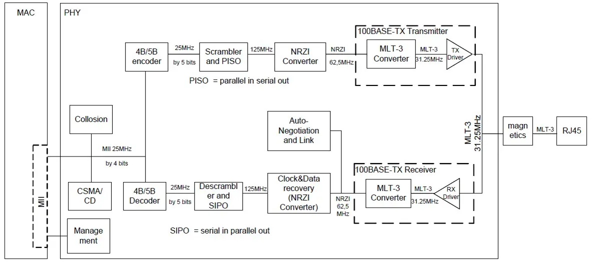
This article delves deeper into the physical layer, detailing components such as the Ethernet PHY, Media Independent Interface (MII) interface, RJ45 jack, magnetic components, and more. Below is the block diagram of the Ethernet PHY in 100Base-TX mode.
Media-Independent Interface (MII)
The Media Independent Interface (MII) connects the PHYTER component to the Media Access Controller (MAC). The MAC may in fact be a discrete device, integrated into a microprocessor, CPU or FPGA.
The IEEE 802.3 standard defines the design and configuration of specific purpose systems that implements the MII interface. The PHY incorporates the Media Independent Interface (MII) as specified in Clause 22 of the IEEE 802.3 standard. This interface is used to connect PHY devices to a MAC. The MII interface consists of a receive bus and a transmit bus each with control signals to facilitate data transfer between the PHY and the upper layer (MAC).
This interface includes a dedicated receive bus and a dedicated transmit bus. These two data buses, along with various control and status signals, allow for the simultaneous exchange of data between the PHY and the upper layer agent (MAC). Additionally, the MII includes the carrier sense signal CRS, as well as a collision detect signal COL. The CRS signal asserts to indicate the reception of data from the network or as a function of transmit data in Half Duplex mode. The COL signal asserts as an indication of a collision which can occur during halfduplex operation when both a transmit and receive operation occur simultaneously.
PHY Management Interface: Management Data Input/Output (MDIO) Interface
All Ethernet PHYs support the IEEE 802.3 MII Management Interface, also referred to as the Management Data Input/Output (MDIO) Interface, enabling upper-layer devices (MAC) to monitor and control the PHY’s state. The MDIO interface comprises a physical connection containing a data line (MDIO), a clock line (MDC), and an optional interrupt line (INTRPT). The MDC operates at a maximum frequency of 25 MHz without a minimum specified frequency. MDIO is bidirectional, facilitating configuration of the MII interface by writing to the Basic Mode Control Register (BMCR) and retrieving link specifications through reading.
|
MII Management |
<idle><start><op code><device addr> <reg addr><turnaround><data><idle> |
|
Read Operation |
<idle><01><10><AAAAA> <RRRRR><Z0><xxxx xxxx xxxx xxxx><idle> |
|
Write Operation |
<idle><01><01><AAAAA> <RRRRR><10><xxxx xxxx xxxx xxxx><idle> |
Typical MDIO Frame Format
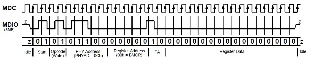
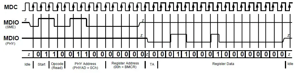
This interface utilizes a specific protocol to enable communication between one controller and multiple PHY devices. Each PHY is assigned an MII address between 0 and 31 via PHYAD inputs, corresponding to a set of fourteen 16-bit MDIO registers. Registers [0:6] are mandatory, defined by IEEE 802.3 specifications, while additional registers offer expanded functionality. The INTRPT pin serves as a management data interrupt, with its active low or high state indicating a PHY status change based on control at the 1fh.9 level. Register bits at 1bh[15:8] control interrupt enablement, while bits at 1bh[7:0] determine interrupt conditions. This interrupt is cleared by reading Register 1bh.
Scrambler
The scrambler is required to control the radiated emissions at the media connector and on the twisted pair cable (for 100BASE-TX applications). By scrambling the data, the total energy launched onto the cable is randomly distributed over a wide frequency range. Without the scrambler, energy levels at the Physical Medium Depend (PMD) and on the cable could peak beyond FCC limitations at frequencies related to repeating 58 sequences (for example, continuous transmission of IDLES).
Parallel to serial converter
The 100BASE-TX receiver incorporates a Parallel to Serial converter, a critical component responsible for converting parallel data symbols into a serialized data stream. This converter processes 5-bit wide data symbols and outputs them in a serial format, which is then forwarded to the Physical Coding Sublayer (PCS) Rx state machine.
NRZ to NRZI Encoder
The NRZ to NRZI encoding process is essential for complying with the Physical Medium Dependent (PMD) standard for 100BASE-TX transmission over Category-X Unshielded Twisted Pair (UTP) cables, such as CAT5, CAT5e, or CAT6. Once the transmit data stream has been serialized and scrambled, NRZI encoding is applied. This encoding scheme converts the Non-Return-to-Zero (NRZ) data stream into Non-Return-to-Zero Inverted (NRZI) format. NRZI encoding alters the signal based on transitions rather than the actual signal level, which helps in synchronization and reduces the number of consecutive identical bits, thus facilitating clock recovery at the receiver end. This process is crucial for ensuring reliable and efficient data transmission over the specified Category-X UTP cables in accordance with the 100BASE-TX standard.
Binary to MLT-3 Converter
MLT-3 encoding (Multi-Level Transmit) is a line code that uses three voltage levels. An MLT-3 interface emits less electromagnetic interference and requires less bandwidth than most the binary or ternary interfaces that operate at the same bit rate The binary to MLT-3 conversion is accomplished by converting the serial binary data stream output from the NRZI encoder into two binary data streams with alternately phased logic one events. These two binary streams are then fed to the twisted pair output driver which converts the voltage to current and alternately drives either side of the transmit transformer primary winding, resulting in a minimal current MLT-3 signal.
Auto-Negotiation
The Auto-Negotiation function provides a mechanism for exchanging configuration information between two ends of a link segment a automatically selecting the highest performance mode of operation supported by both devices. Fast Link Pulse (FLP) Bursts provide the sig used to communicate Auto-Negotiation abilities between two devices at each end of a link segment.
The Auto-Negotiation function automatically configures the PHY to optimal link parameters based on the capabilities of its link partners. T twisted-pair Auto-Negotiation system included all three speeds of Ethernet supported over twisted-pair cable: 10Mbit/s 10Base-T, 100Mbi 100Base-TX and 1000 Mbit/s 1000Base-T. The physical signaling portion of all three twisted pair systems uses the same Auto-Negotiation signaling standard. While Auto-Negotiation can be disabled on 10Base-T and 100Base-TX links, it is required on 1000Base-T systems since Gigabit Ethernet systems use Auto-Negotiation to establish the master-slave signal timing control required to make the link operational.
Twisted-pair link partners can use Auto-Negotiation to figure out the highest speed that they each support, for example, as well as automatically setting full-duplex operation if both ends support that mode. If two Auto-Negotiation devices with multiple capabilities are connected together they find their highest performance mode of operation based on a priority
Table ranked from the highest to the lowest as below.
|
A |
100Base-TX Full Duplex |
|
B |
100Base-T4 |
|
C |
100Base-TX |
|
D |
10Base-T Full Duplex |
|
E |
10Base-T |
Summary
The Ethernet Physical Layer (PHY) is a crucial component of Ethernet networking, responsible for transmitting and receiving data over the physical medium. In 100Base-TX mode, the PHY comprises several key components and interfaces:
- Media Independent Interface (MII): Connects the PHY to the Media Access Controller (MAC), facilitating data transfer between them. It consists of separate receive and transmit buses, along with control and status signals like CRS (carrier sense) and COL (collision detect).
- PHY Management Interface (MDIO): Also known as IEEE 802.3 MII Management Interface, it allows upper-layer devices (MAC) to monitor and control the PHY’s state. It includes data (MDIO), clock (MDC), and optional interrupt (INTRPT) lines.
- Scrambler: Required to control radiated emissions and prevent energy peaking beyond FCC limitations by scrambling data, distributing energy over a wide frequency range.
- Parallel to Serial Converter: Converts parallel data symbols into a serialized data stream for further processing.
- NRZ to NRZI Encoder: Essential for complying with the 100BASE-TX standard, converting Non-Return-to-Zero (NRZ) data into Non-Return-to-Zero Inverted (NRZI) format, aiding in synchronization and clock recovery.
- Binary to MLT-3 Converter: Converts binary data into Multi-Level Transmit (MLT-3) encoding, emitting less electromagnetic interference and requiring less bandwidth.
- Auto-Negotiation: Facilitates the exchange of configuration information between link partners, automatically selecting the highest performance mode supported by both devices. It is essential for establishing optimal link parameters and is required for Gigabit Ethernet systems.
Author Profile
- 20+ years embedded hardware design professional with a burning passion for teaching. Sharing the intricate world of embedded hardware is my mission and joy.
Latest entries
 Tech Updates30 November 2025STM32WBA6: The Next-Generation MCU Powering Secure Short-Range Wireless Designs
 Blogs24 November 2025High-Speed PCB Layout Design Guide-104
 Tech Updates14 September 2025Renesas Launches RL78/L23 Ultra-Low-Power MCUs to Power Smarter Home Appliances
 Blogs7 September 2025High-Speed PCB Layout Design Guide-103


